
IS-IS Overview
Intermediate system to intermediate system (Short for IS-IS) is an IGP link-state protocol which builds a link-state database. Like OSPF, It will the run the Dijkstra SPF algorithm to find the best path to the destination. IS-IS has an AD of 115 with Cisco NX-OS.
Unlike OSPF, IS-IS does not run over network layer. It encapsulates IS-IS messages directly into data-link frames.
ISIS can exchange any information not just IPv4 routes. You can even exchange MAC addresses or IPv6. With TLV (Type, Length, Value) fields in ISIS packets, the protocol does not to be rewritten.
What are CLNS and CLNP
Equivalent of IP/IPv6 to TCP/IP is Connectionless-mode Network Protocol (CLNP) to OSI model. IP connects the hosts by a router. CLNP connects the End-Systems (ES) by an Intermediary-System (IS).
CLNP provides a set of services known as Connectionless-mode Network Service (CLNS). CLNS runs over CLNP and refers to a router’s operation including IS-IS on OSI connectionless mode. In CLNS:
- hosts talk to each other using CLNP (not IP)
- hosts talk to router using ES-IS protocol
- Intermediary-systems talk to each other using IS-IS or ISIS
Network Service Access Point (NSAP)
Network Service Access Point (NSAP) addressing is what we use in OSI networks. Unlike IP where you assign the address directly to the interface, with NSAP you assign the address to the entire node.
NSAP Addressing Scheme
The length for NSAP is minimum of 8 and maximum of 20 Bytes.
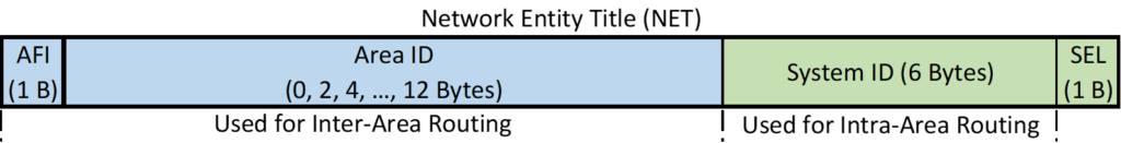
If 39<=AFI<=49, it is reserved for private networks by ISO. 47 and 49 are popularly used for IP private domains.
SEL field also called an NSAP Selector or NSEL is always 00 for IS. In this case – with SEL=0 – the NSAP address is called Network Entity Title (NET).
Within the area we only use system ID as part of SPF calculation
Here are some example of NET addresses:
- NET: 49.0001.0000.0000.1111.00
- AFI is 49
- Area number is 0001
- System ID is 0000.0000.1111
- SEL value: 00
Levels of Routing in OSI Networks
- Level 0 routing (ES-IS):
- Routing between an End System (host) and its IS (router); In IP world we have Proxy ARP, IPv6 ND, or default gateway.
- Level 1 routers:
- Analogous to OSPF non-backbone Internal Routers
- Level 2 routers:
- Analogous to OSPF backbone Internal Routers
- Usually a single L2 area in Service Provides
- Level1/Level2 outers:
- Analogous to OSPF ABRs.
- Default router type is this type with NX-OS
- Level 3 routing:
- Analogous to BGP in TCP/IP world.
- MPBGP obsoletes L3 routing even with OSI
N9K01# configure terminal
N9K01(config)# feature isis
N9K01(config)# router isis 1
N9K01(config-router)# net 49.0001.0000.0000.1111.00
N9K01(config-router)# address-family ipv4 unicast

N9K01(config-router-af)# exit
N9K01(config-router)# is-type level-1
N9K01(config-router)# log-adjacency-changes
N9K01(config)# interface ethernet 1/1
N9K01(config-if)# ip router isis 1
N9K01(config-if)# ip address 10.1.1.1/31
IS-IS Network Types
With IS-IS we only have two network types:
- Broadcast:
- Uses Designated Intermediate System (DIS) instead of DR/BDR.
- Point-to-point
- Most case in Datacenter network. So, we will change our network types to point-to-point to suppress the DIS election process.
To form an adjacency, the network types must match.
! Configure point-to-point network type
N9K01# configure terminal
N9K01(config)# interface ethernet 1/1
N9K01(config-if)# medium p2p
! Configure broadcast network type
N9K01# configure terminal
N9K01(config)# interface ethernet 1/1
N9K01(config-if)# medium broadcast
IS-IS Adjacencies
IS-IS sends Hello PDUs every 10 seconds. The default Hello multiplier is 3, resulting a Hold time of 30 seconds. To form an adjacency, MTU, Network type, and level of adjacency must match. In case of L1 adjacency, area also must match.
- L1-only routers form L1 adjacencies with L1 and L1/L2 neighbors – only if their AIDs match.
- L2-only routers form L2 adjacencies with L2 and L1/L2 neighbors – even if their AIDs don’t match.
- Two L1/L2 Routers form both L1 and L2 adjacencies if their AIDs match.
- Two L1/L2 routers form only an L2 adjacency if their AIDs do not match.
IS-IS Adjacency States
- Down: The initial state.
- Initializing: IS-IS neighbor received IS-IS Hellos, but it is not certain that the neighbor is properly receiving this router’s Hellos.
- Up: IS-IS neighbor received IS-IS Hellos, and it is certain that the neighbor is properly receiving this router’s Hellos.
IS-IS Workshop
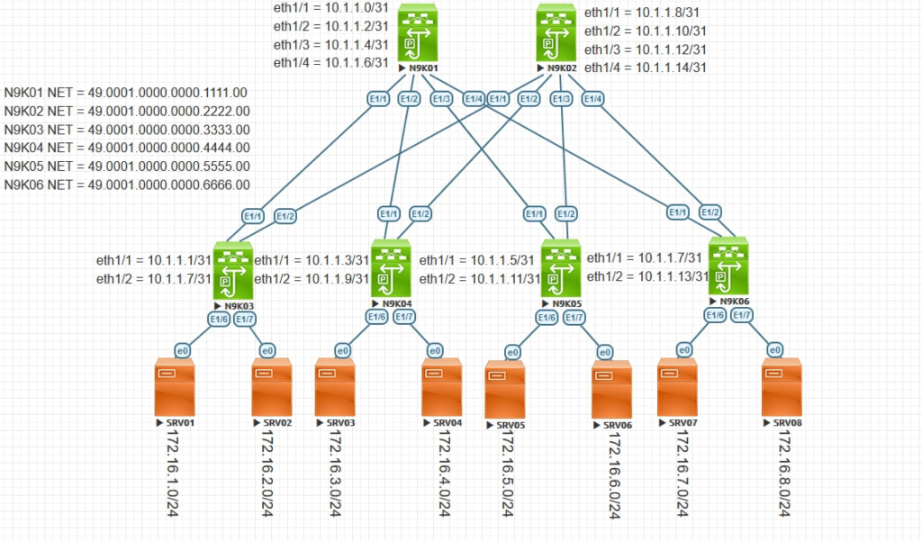
For the purpose of this workshop we are going to consider the following leaf-and-spine topology.
Configuration
N9K01
configure terminal
    feature isis
  interface Ethernet1/1
     no switchport
     ip address 10.1.1.0/31
     no shutdown
    interface Ethernet1/2
     no switchport
     ip address 10.1.1.2/31
     no shutdown
    interface Ethernet1/3
     no switchport
     ip address 10.1.1.4/31
     no shutdown
    interface Ethernet1/4
     no switchport
    ip address 10.1.1.6/31
     no shutdown
    router isis 1
      net 49.0001.0000.0000.1111.00
    address-family ipv4 unicast
    is-type level-1
    log-adjacency-changes
    interface ethernet 1/1-4
      ip router isis 1
     medium p2p
    exit
N9K02
configure terminal
    feature isis
  interface Ethernet1/1
     no switchport
     ip address 10.1.1.8/31
     no shutdown
    interface Ethernet1/2
     no switchport
     ip address 10.1.1.10/31
     no shutdown
    interface Ethernet1/3
     no switchport
     ip address 10.1.1.12/31
     no shutdown
    interface Ethernet1/4
     no switchport
    ip address 10.1.1.14/31
    router isis 1
      net 49.0001.0000.0000.2222.00
    address-family ipv4 unicast
    is-type level-1
    log-adjacency-changes
    interface ethernet 1/1-4
      ip router isis 1
     medium p2p
    exit
N9K03
configure terminal
    feature isis
  interface Ethernet1/1
     no switchport
     ip address 10.1.1.1/31
     no shutdown
    interface Ethernet1/2
     no switchport
     ip address 10.1.1.9/31
     no shutdown
  interface Ethernet1/6
     no switchport
     ip address 172.16.1.1/24
     no shutdown
    interface Ethernet1/7
     no switchport
     ip address 172.16.2.1/24
     no shutdown
    router isis 1
      net 49.0001.0000.0000.3333.00
    address-family ipv4 unicast
    is-type level-1
    log-adjacency-changes
    interface ethernet 1/1-2
      ip router isis 1
     medium p2p
  interface ethernet 1/6-7
  ip router isis 1
    exit
N9K04
configure terminal
    feature isis
  interface Ethernet1/1
     no switchport
     ip address 10.1.1.3/31
     no shutdown
    interface Ethernet1/2
     no switchport
     ip address 10.1.1.11/31
     no shutdown
  interface Ethernet1/6
     no switchport
     ip address 172.16.3.1/24
     no shutdown
    interface Ethernet1/7
     no switchport
     ip address 172.16.4.1/24
     no shutdown
    router isis 1
      net 49.0001.0000.0000.4444.00
    address-family ipv4 unicast
    is-type level-1
    log-adjacency-changes
    interface ethernet 1/1-2
      ip router isis 1
     medium p2p
  interface ethernet 1/6-7
  ip router isis 1
    exit
N9K05
configure terminal
    feature isis
  interface Ethernet1/1
     no switchport
     ip address 10.1.1.5/31
     no shutdown
    interface Ethernet1/2
     no switchport
     ip address 10.1.1.13/31
     no shutdown
  interface Ethernet1/6
     no switchport
     ip address 172.16.5.1/24
     no shutdown
    interface Ethernet1/7
     no switchport
     ip address 172.16.6.1/24
     no shutdown
    router isis 1
      net 49.0001.0000.0000.5555.00
      address-family ipv4 unicast
      is-type level-1
    log-adjacency-changes
  interface ethernet 1/1-2
    ip router isis 1
     medium p2p
    interface ethernet 1/6-7
    ip router isis 1
    exit
N9K06
configure terminal
    feature isis
  interface Ethernet1/1
     no switchport
     ip address 10.1.1.7/31
     no shutdown
    interface Ethernet1/2
     no switchport
     ip address 10.1.1.15/31
     no shutdown
  interface Ethernet1/6
     no switchport
     ip address 172.16.7.1/24
     no shutdown
    interface Ethernet1/7
     no switchport
     ip address 172.16.8.1/24
     no shutdown
    router isis 1
      net 49.0001.0000.0000.6666.00
      address-family ipv4 unicast
      is-type level-1
    log-adjacency-changes
  interface ethernet 1/1-2
    ip router isis 1
     medium p2p
    interface ethernet 1/6-7
    ip router isis 1
    exit
Verification
To display on which interfaces the IS-IS is configured:
N9K01# show isis interface brief
IS-IS process: 1 VRF: default
Interface    Type  Idx State        Circuit   MTU  Metric  Priority  Adjs/AdjsUp
                                                   L1  L2  L1  L2    L1    L2
--------------------------------------------------------------------------------
Topology: TopoID: 0
Ethernet1/1  P2P   1     Up/Ready   0x01/L1   1500 40  40  64  64    1/1   0/0
Topology: TopoID: 0
Ethernet1/2  P2P   2     Up/Ready   0x01/L1   1500 40  40  64  64    1/1   0/0
Topology: TopoID: 0
Ethernet1/3  P2P   3     Up/Ready   0x01/L1   1500 40  40  64  64    1/1   0/0
Topology: TopoID: 0
Ethernet1/4  P2P   4     Up/Ready   0x01/L1   1500 40  40  64  64    1/1   0/0
After configuration, let’s check the adjacency:
N9K01# show isis adjacency
IS-IS process: 1 VRF: default
IS-IS adjacency database:
Legend: '!': No AF level connectivity in given topology
System ID       SNPA            Level  State  Hold Time  Interface
N9K03           N/A             1      UP     00:00:29   Ethernet1/1
N9K04           N/A             1      UP     00:00:29   Ethernet1/2
N9K06           N/A             1      UP     00:00:25   Ethernet1/3
N9K06           N/A             1      UP     00:00:25   Ethernet1/4
Once the adjacencies established, let’s check what LSDB is formed on the router as shown below:
N9K01# show isis database
IS-IS Process: 1 LSP database VRF: default
IS-IS Level-1 Link State Database
  LSPID                 Seq Number   Checksum  Lifetime   A/P/O/T
  N9K01.00-00         * 0x0000000C   0xC9F3    1062       0/0/0/1
  switch.00-00          0x0000000F   0x4A7C    1064       0/0/0/1
  N9K03.00-00           0x00000018   0x9382    800        0/0/0/1
  N9K04.00-00           0x00000007   0x9659    884        0/0/0/1
  N9K06.00-00           0x00000007   0x8F28    987        0/0/0/1
  N9K06.00-00           0x00000007   0xD0B0    1068       0/0/0/1

IS-IS Level-2 Link State Database
  LSPID                 Seq Number   Checksum  Lifetime   A/P/O/T
In the end, let’s check what SPF calculated to populate the routes:
N9K01# show ip route isis-1
IP Route Table for VRF "default"
'*' denotes best ucast next-hop
'**' denotes best mcast next-hop
'[x/y]' denotes [preference/metric]
'%<string>' in via output denotes VRF <string>

10.1.1.8/31, ubest/mbest: 1/0
    *via 10.1.1.1, Eth1/1, [115/80], 00:07:36, isis-1, L1
10.1.1.10/31, ubest/mbest: 1/0
    *via 10.1.1.3, Eth1/2, [115/80], 00:05:54, isis-1, L1
10.1.1.12/31, ubest/mbest: 1/0
    *via 10.1.1.5, Eth1/3, [115/80], 00:04:19, isis-1, L1
10.1.1.14/31, ubest/mbest: 1/0
    *via 10.1.1.7, Eth1/4, [115/80], 00:02:57, isis-1, L1
172.16.1.0/24, ubest/mbest: 1/0
    *via 10.1.1.1, Eth1/1, [115/80], 00:07:29, isis-1, L1
172.16.2.0/24, ubest/mbest: 1/0
    *via 10.1.1.1, Eth1/1, [115/80], 00:07:28, isis-1, L1
172.16.3.0/24, ubest/mbest: 1/0
    *via 10.1.1.3, Eth1/2, [115/80], 00:05:54, isis-1, L1
172.16.4.0/24, ubest/mbest: 1/0
    *via 10.1.1.3, Eth1/2, [115/80], 00:05:54, isis-1, L1
172.16.5.0/24, ubest/mbest: 1/0
    *via 10.1.1.5, Eth1/3, [115/80], 00:04:19, isis-1, L1
172.16.6.0/24, ubest/mbest: 1/0
    *via 10.1.1.5, Eth1/3, [115/80], 00:04:19, isis-1, L1
172.16.7.0/24, ubest/mbest: 1/0
    *via 10.1.1.7, Eth1/4, [115/80], 00:02:57, isis-1, L1
172.16.8.0/24, ubest/mbest: 1/0
    *via 10.1.1.7, Eth1/4, [115/80], 00:02:57, isis-1, L1
References
It is not necessary for CCIE Datacenter curriculum, but you can refer to this link to compare Link-State and Distance-Vector protocols.
You could also refer to this link to understand different variations of SPF algorithm.

remarkable content