ISO/OSI Model; Open Systems Interconnection
OSI stands for Open Systems Interconnection, it is a model which tells us how the application communicates over a network. Basically, seven marvelous layers that IT systems use to communicate and disseminate data over network, established in 1983 by the International Organization for Standardization (ISO) and became a working product of the OSI group at the ISO, it was approved as an international standard for communications architecture. the history doesn’t make a conception comprehensible for us, then it’s only remarkable to know. It is a well-organized structure which enable many systems to connect with each other and diffuse data. This structure entail seven different layers each of which is selected to perform a well-defined function at a different level of abstraction. The bottom three layers provide for the timely and correct transfer of data, and the top four ensure that arriving data are recognizable and useful. While all seven layers are usually necessary at each user location, only the bottom three are normally employed at a network node, since nodes are concerned only with timely and correct data transfer from point to point.
Models which are formed a definition of layered architecture
Oracle illustrates the conception of a model as a way to organize a system’s functions and features to define its structural design. A design can help us understand how a communication system accomplishes tasks to form a protocol suite. Models are routinely organized in a hierarchical or layered structure. Each layer has a set of functions to perform. Protocols are created to handle these functions, and therefore, protocols are also associated with each layer. The protocols are collectively referred to as a protocol suite.
Historical Models was supposed to perpetuate the communications but forgotten
- Systems Network Architecture (SNA-IBM)
- AppleTalk
- Novell Netware (IPX/SPX)
Those modeling of the Communication Systems were subjugated by a true hero named TCP/IP in conformity with their own reference model called OSI.
The Open Systems Interconnect (OSI) reference model is the basis of commercially available network service architectures. Other network protocols, developed independently, conform loosely to the model. The TCP/IP Internet Protocol suite is an example.
OSI model is founded to follow the particular purposes
- To standardized data networking protocols to allow communication between all networking devices across the entire planet.
- To create a common platform for software developers and hardware manufactures that encourage the creation of networking products that can communicate with each other over the network.
- To help network administrators by dividing large data exchange process into smaller segments. Smaller segments are easier to understand, manage and troubleshoot.
Previous
Next
Story Telling
The OSI reference model is a convenient framework for networking concepts. Basically, data are injected into a network by a sender. The data are transmitted along a communication connection and are delivered to a receiver. To do this, a variety of networking hardware and software must work together.
Advantages of the OSI Model
- Help network engineers in determining the required hardware and software to build their network.
- Encourage hardware manufacturers to create networking products that can communicate with each other over the network.
- Provide a teaching tool to understand the communication process used between networking components.
- Separate a complex function into simpler components.
- Make troubleshooting easier, as network administrators can troubleshoot issues more quickly and effectively by looking in a layer that is causing the issue rather than finding it in the entire network.
Disadvantages of OSI Model
- It defines various services multiple times. For example, the error control service is defined in both Transport and Data Link layers.
- It does not allow layers to work parallel. A layer has to wait till it gets data from its predecessor layer.
- Instead of defining similar functions in the same layer, it defines them in different layers that add additional complexity.
- Instead of providing a summary of rarely used protocols and functions, it defines every protocol and function in detail that makes the model lengthy and less useful for administrators.
Characteristics of the OSI Layers
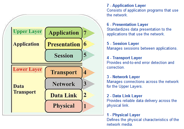
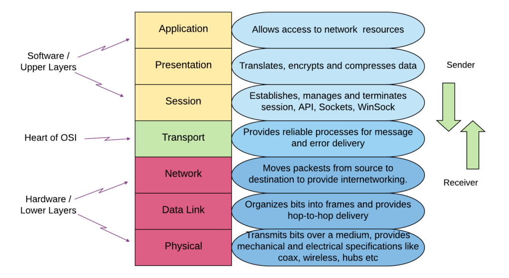
The seven layers of the OSI reference model can be divided into two categories: upper layers and lower layers.
The Upper Layers of the OSI model deal with application issues and generally are implemented only in software. The highest layer, the application layer, is closest to the end user. Both users and application layer processes interact with software applications that contain a communications component. The term upper layer is sometimes used to refer to any layer above another layer in the OSI model.
The Lower Layers of the OSI model handle data transport issues. The physical layer and the data link layer are implemented in hardware and software. The lowest layer, the physical layer, is closest to the physical network medium (the network cabling, for example) and is responsible for actually placing information on the medium.
Britannica have already formed an amazing preconception of layering:
Data recognition and use
Application Layer
Presentation Layer
Session Layer
Transport Layer
Application Layer
distributed databases used in the banking and airlines industries.
Presentation Layer
Text conversion, data compression and data encryption.
Session Layer
User interface with the network is performed by the session layer, which handle the process of connecting to another computer, verifying user authenticity, and establishing a reliable communication process. This layer also ensures that files which can be altered by several network users are kept in order.
Transport Layer
separates the data stream into smaller unit, if necessary, and ensures that all arrive correctly at the destination.
Data Transfer
Network Layer
Data-link Layer
Physical Layer
Network Layer
breaks data into packets and determines how the packets are routed within the network.
Data-link Layer
transforms a raw communications channel into a line that appears essentially free of transmission errors to the network layer. This is done by breaking data into data frames, transmitting them sequentially, and processing acknowledgment frames sent back to the source by the destination.
Physical Layer
is the transmission medium itself, along with various electric and mechanical specifications.
ICS – OPEN SYSTEMS INTERCONNECTION (OSI)
TCP/IP Model
TCP/IP Model – This model is sometimes called the DOD model since it was designed for the department of defense. It is also called the internet model because TCP/IP is the protocol used on the internet.
Architecture of Current networks operates in accordance with TCP/IP model
at the moment, data transmission networks do not use the OSI reference model they take advantage of TCP/IP. In spite of this almost all networking courses and networks projects analysis consider the OSI model. OSI terminology become commonplace in the world of networking and many vendors and engineers began to use them. The most brilliant facet of being popular is that OSI strives to describe every concept, function and protocol in detail. Once you learn this model you can easily expand over the TCP/IP notions by learning the difference between the two models.
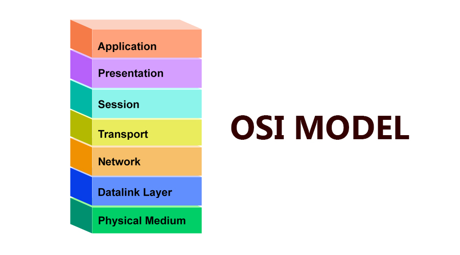
The OSI Model can be seen as a universal language for computer networking. It’s based on the concept of splitting up a communication system into seven abstract layers, each one stacked upon the last.
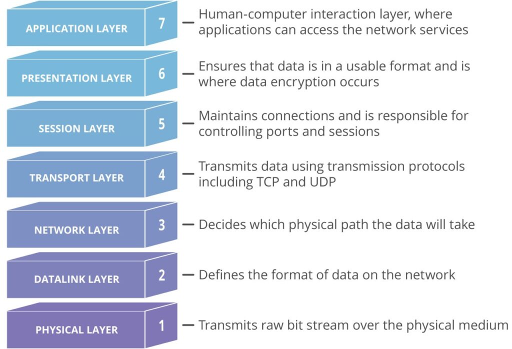
Each layer of the OSI Model handles a specific job and communicates with the layers above and below itself.
How Data Flows through the OSI Layers
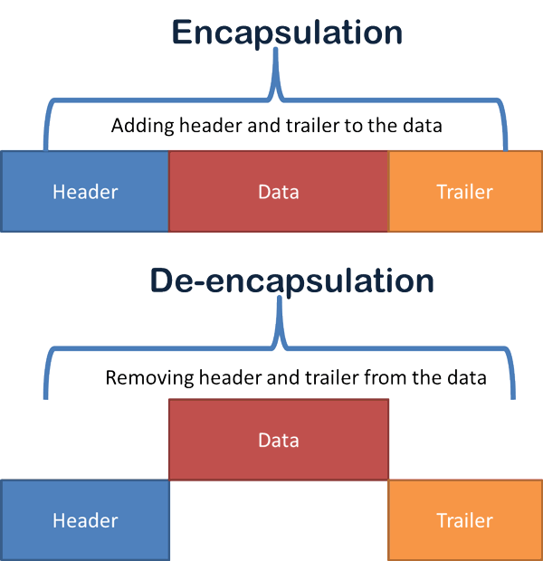
To get a better understanding of how the OSI layers function, it is important to know how data flows between the layers. we’ll trace the data as it flows through the layers of the OSI model. As you will see, each layer adds (or encapsulates) some form of header or trailer. (Layer 2, the Data Link layer, is responsible for adding a trailer.)
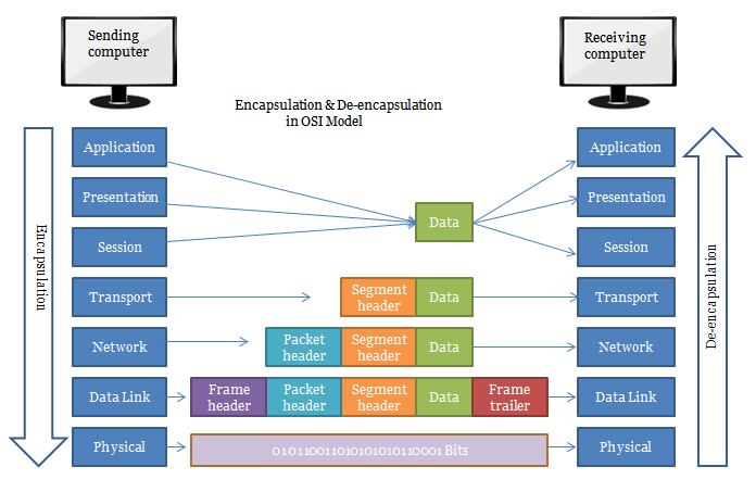
The example demonstrates how end user packets (header and data) flow through the OSI model. we assume there are no intermediate devices.
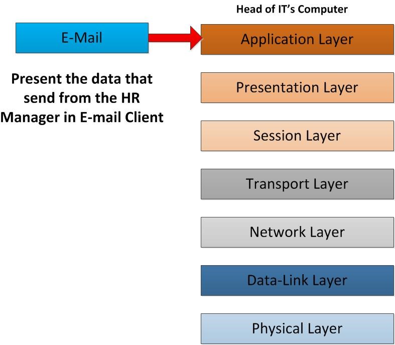
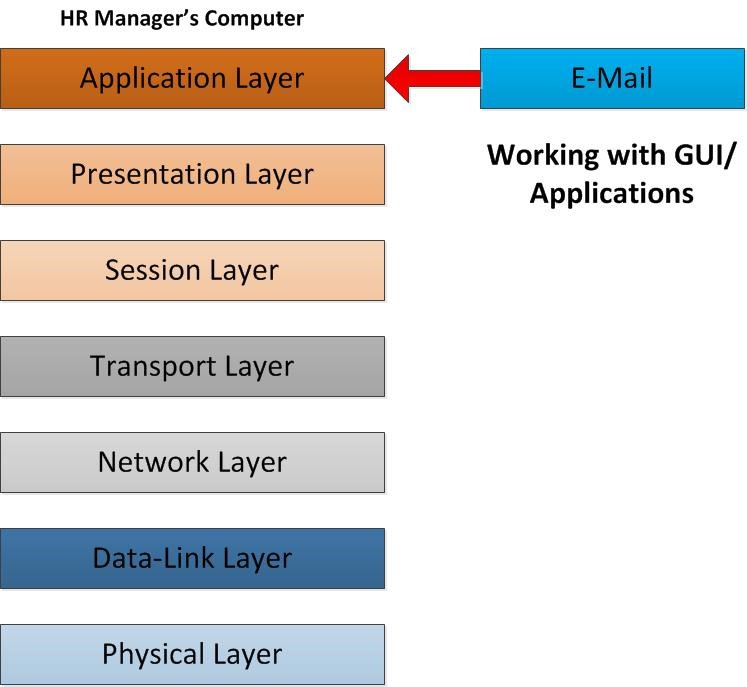
When the end system receives the unstructured bit stream from the physical wire, each layer removes the header information applicable to it until the application receives the data. The following depicts what occurs in the OSI model’s layers when sending an email on the internet consequently the request is sent from Device A to Device B. Data flows from layer 7 down to layer 1 from the sender, and then flows from layer 1 to layer 7 on the recipient device.
I’ve figured out Dishan M. Francis draw my undivided attention to the data flows by giving this example; When computer communicates with another host, it’s goes through all 7 layers top to bottom or bottom to top. In one side these layers can talk to its upper layer or lower layers. Each of these layers talks to the corresponding layer in the other side when it communicates. For ex- application layer from one end will only talk to application layer on the other side. It cannot talk to any other layer which means application layer cannot talk to presentation layer on the other side.
![]()
So, let’s move in to the given scenario. As the first step a client sends the email. To sends the email from his/her computer he/she may using email client. It can be outlook express, MS office outlook, Thunderbird, Mac mail etc. This process is goes in to Application Layer of the OSI model. It provides the interface for the user to tell the computer how to handle the data. In this scenario since its emails the email client will use SMTP protocol and command to tell computer how to handle those data.
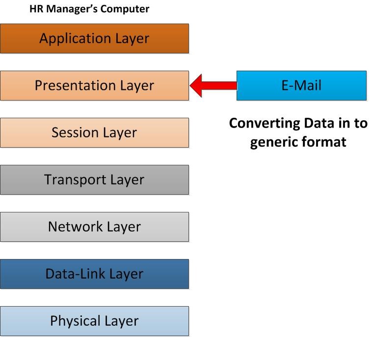
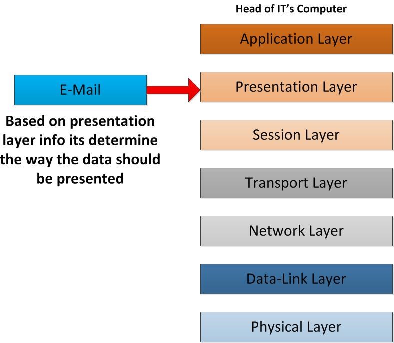
Then the email initiates to operate on the Presentation Layer of the OSI model. In this layer the email content will be converting in to network formats. It defines how the data will be presented. So, the E-mail text will be converting in to ASCII and images will specify as TIFF, JPEG, etc. other important thing that will happen in this layer is data encryption and data compression. With encryption it defines the how secure communication would be happened going down through the OSI Layer. For example, in this layer you can use SSL (secure socket layer) for the encryption of the data.
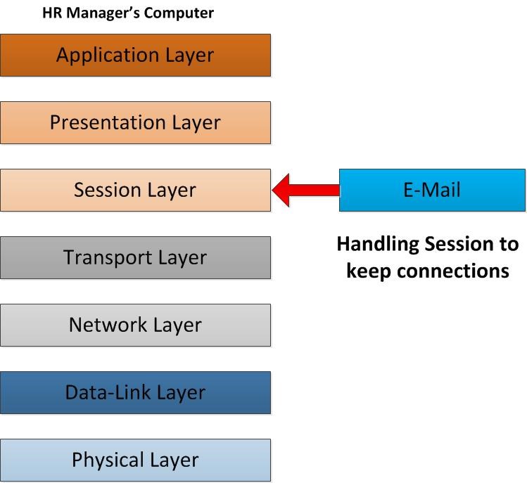
As the email starts operating in session layer, it will be responsible for establishing, maintaining and terminating the connection with the other end. So, in this scenario the session layer responsible to preserve the connection with the other client which is waiting to receive the email, in order to deliver the email correctly. In that computer currently it’s not only one connection made to different hosts. For example, while HR manager send email, he may also visit a website on the internet. while data packets sending and receiving how a computer knows which packet of data should deliver to this application? The answer lies in the functionality of session layer. Session layer establishes, manage and terminate the “connections” to the relevant host. This is accomplished by using the port numbers. It separates and isolates the connections using random ports, furthermore the sessions are not mixed up. Without sessions the data will not flow through the OSI Layers timely and correctly.
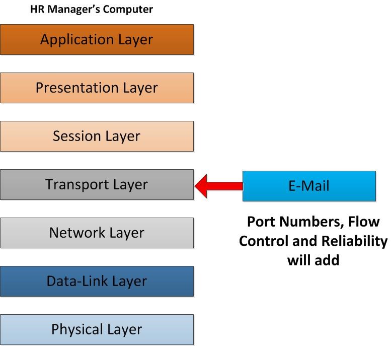
As email descending to the next layer, it operates in transport layer. This is the layer which will play the role of reliability and the flow control. email data from that client will break into segments to transmit over. It should be clarified that which protocol could be TCP or UDP. In a way of using TCP, it reaches out the reliability. It’s always acknowledging the transfer of the data packet. from sender end once TCP packet go to receiver end it confirms as the packet is received so sender always know the packet is transfer properly as he/she wishes. UDP in other side provides faster way of transmitting but no reliability. It doesn’t provide any acknowledgment of packet transfer. In this scenario the email will use TCP port number 25 which use the SMTP protocol. Sender port as well the receiver port will define in this layer, since receiver also get it as email it would be configured on port 25. It’s going to be reliable data packet transfer. Another important item is that it breaks data into segments; once the other parties receive the packet, he/she should be able to reassemble it in a correct order. This flow control also defines by this layer. When other user receives these packets, he/she can reassemble it in a correct order.
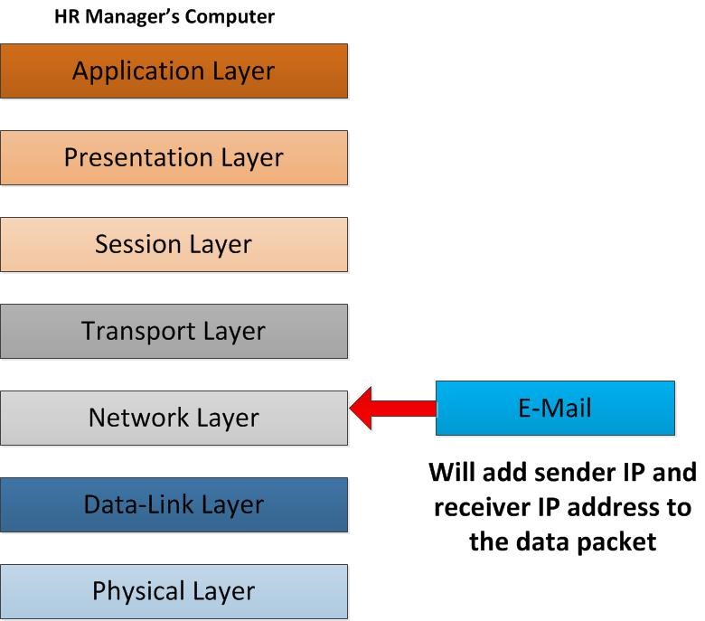
As the email data packet flows into network layer, it defines how the routing of this data packet will happens. For transmitting packets of data across network should be a particular procedure which gives an opportunity to reach the destination among numerous hosts. It’s the same as sending a postal mail to someone in somewhere. in this layer from sender client’s computer to the receiver client’s computer it will clarify the routes and the best path towards the proper destination. During the operation of this layer, the sender IP address and receiver IP address will be added to the packet of data. Now each data packet knows where it should go to.
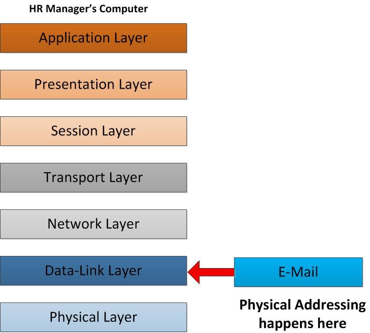
As the packet move further down along the layers, it reaches the Data Link layer. Now the email data packet will be prepared to send over the Ethernet. It is undeniable that the data packet will be encapsulated in data frames. As we know in network layer the packet was modified with the sender and the receiver IP address. hence the data receives by network destination how exactly it knows where it should be delivered? The recipient may check emails from a different network which there are a lot of computers operating on that. Data link strives to retrieve the Physical address also known as MAC address to the data frame. MAC address is a unique physical address assigned to each network adaptor in a computer or network devices. As a result of using MAC, frames could find out a way to achieve their proper host. The sender and receiver MAC address will be added to the frame.
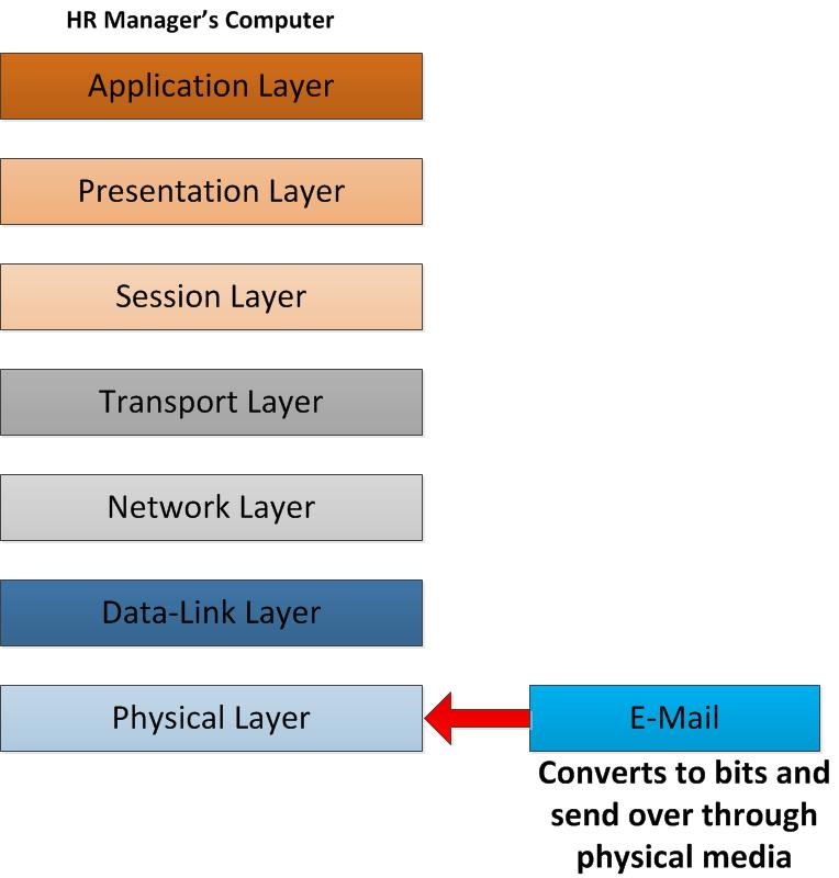
Now the data is ready for transmitting over a medium to the receiver side. Whitin physical layer the data frame will be converted into bits. After it converts it will be sent over the physical media which means through your NIC, Ethernet Cable, Wireless connection and vast numbers of various infrastructures.
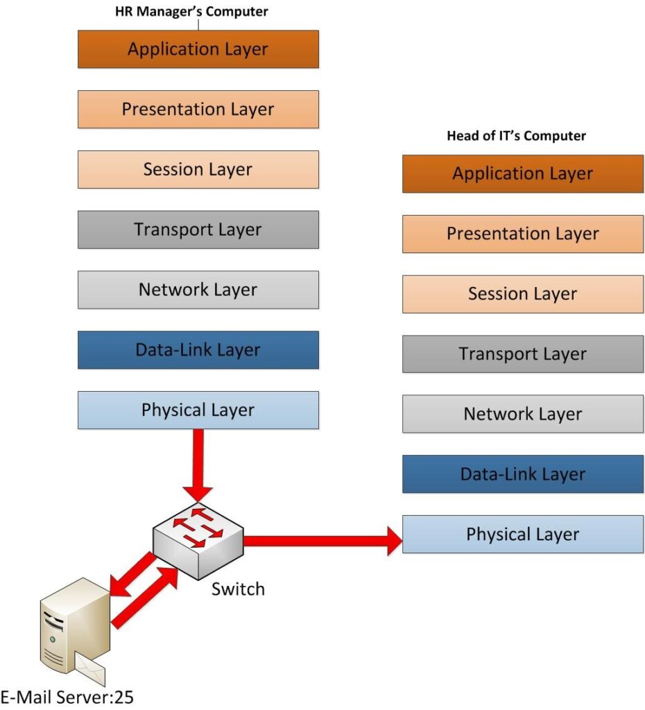
Now the data frames are off from the sender machine. Now it’s in its way to receiver end. But still, it has to pass several major points. As soon as it leaves the NIC, the first place will be the switch that sender computer is connected to. So, the only layers it will operate in this process is the data-link layer and physical layer which means the source and destination of MAC address within the frame HDR will be modified. in given scenario the sender MAC belongs to HR manager’s NIC and destination Mac is going to be the switch port. That’s the only change will happened in data frame. Then it will look for the E-mail Server for delivering email. In this scenario I assumed it’s in same office environment. it searches for the E-mail server and its header again get modified with the MAC addresses so destination will be E-mail server NIC Mac address and sender is the switch port MAC. Now switch checks weather this destination can be reach. The same time remember it’s removed the old data link layer MAC address as those no need. if switch can find it in its ARP table, the data frame will travel towards the NIC of the E-mail Server. If it cannot find, it sends this to network layer where routers are working so its check network layer and check if original destination of email server is in same network or not and if not, it sends it out as it knows how to handle those paths. And then it will go point to point with modifying its headers based on destinations.
But here I had assumed it’s connected in same network so it will not reach out via router. Once E-mail server receives the request it will process and send it to receiver’s mail box. Then again email server will send the new data frame to the switch to process it towards the receiver. In that frame again the data link layer headers will be modified and added the new destination and sender MAC address. Then switch again have to find the receiver destination. The process is exactly the same as it follows to find the email server for the first one. Once it found the correct port the data frames will be delivering via Ethernet cable which is works under physical layer.
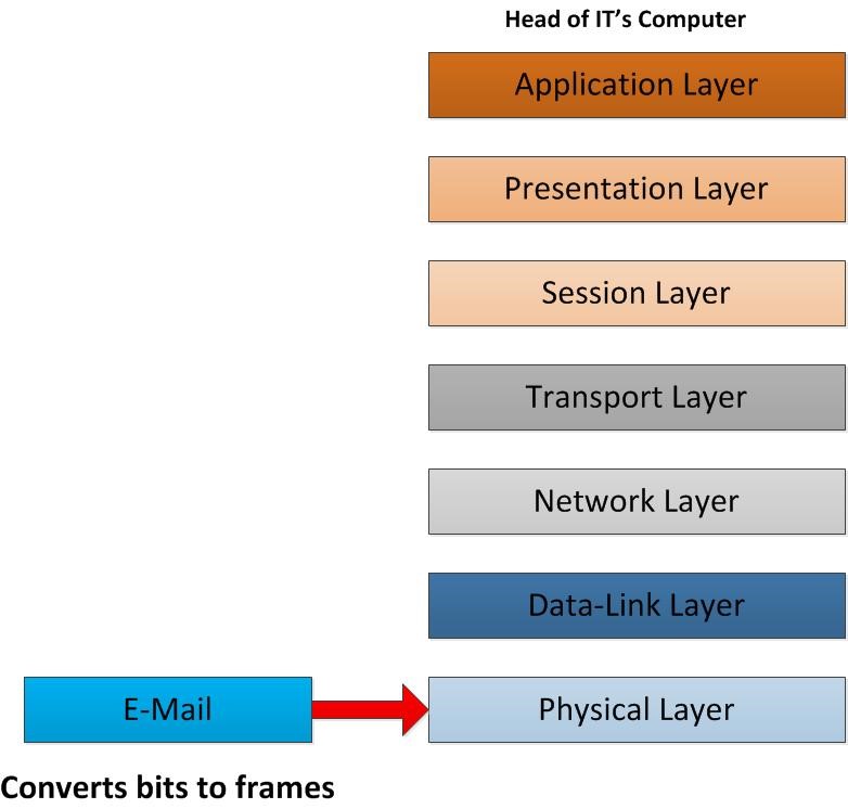
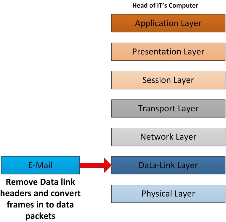
thus, it reaches the NIC card of the receiver end which means the physical layer of the other end, it begins to remove the header information that was added from the sender. In the physical layer it will convert the bitstreams into the data frames and send it for further process to data-link layer.
when data frame comes into data-link layer, removing the related header of the frame which was employed in the corresponding data-link layer consists MAC addresses. Then it converts that frames into the IP Packets. After that it will be sent to network layer.
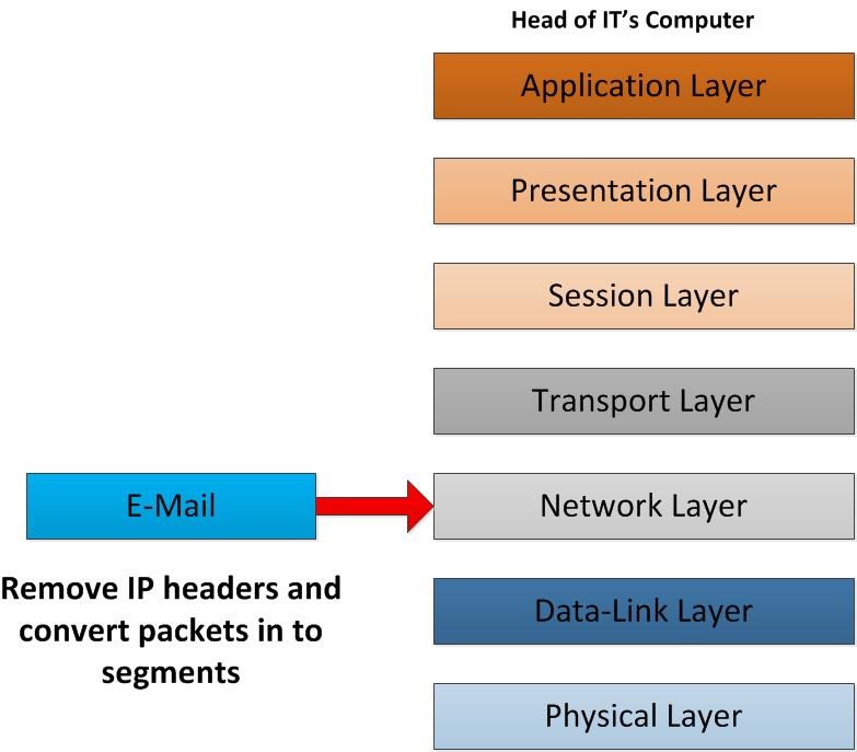
Once network layer receives the packets, it removes the IP header information. This will include all the information about the sender IP address and Receiver IP Address. After removing those related HDR, IP packets will be converted into segments and sent to transport layer.
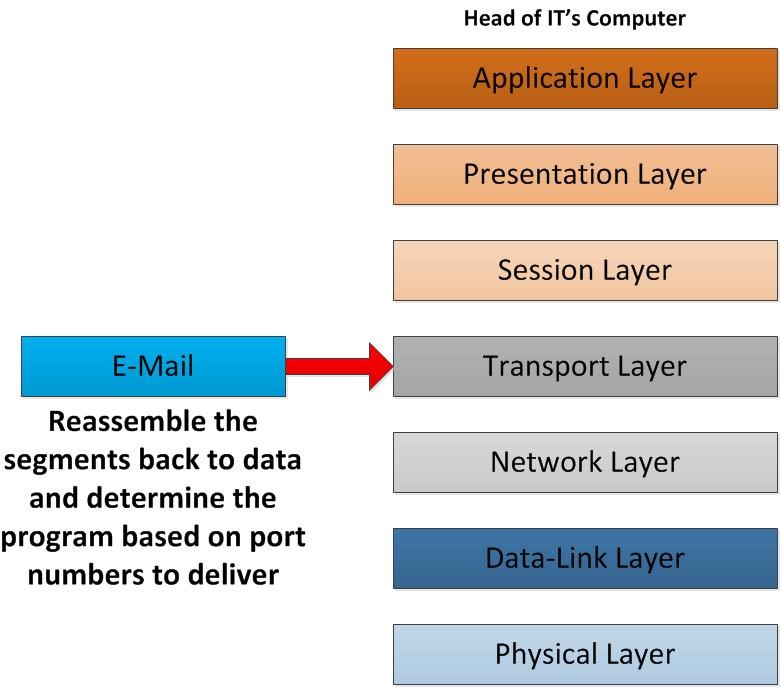
When segments move to the transport layer, based on the protocol it used, TCP/UDP, in conformity with the functions which happens in the transport layer will reassemble them in to the order. In sender side it was break the data into segments before transmitting. In receiver end it needs to make into proper order and make the actual data of it. Another important thing is that it reads the port that used in the segments and determines which application the data should deliver to. Based on the fact that it identifies as HTTP, SNMP, FTP traffic. In our scenario, SMTP TCP Port 25 would be correct. After converts this segments to actual data it will pass to session layer.
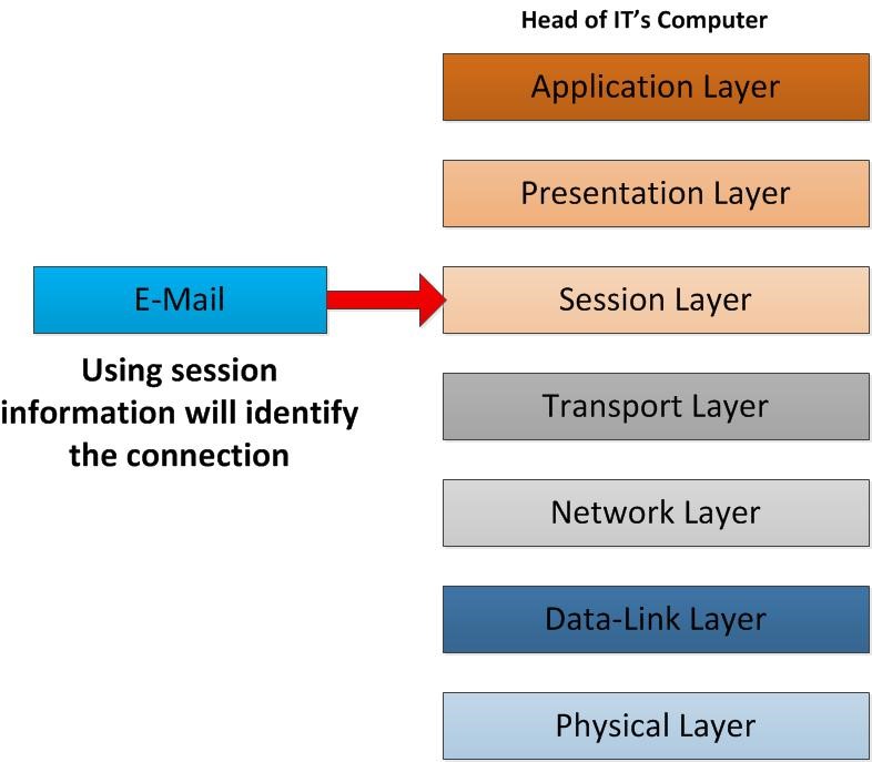
hence data reaches the session layer based on session information it will identify the communication type, this data belongs to. Let’s say user have few email applications such as outlook express, incredimail etc. all these are working with SMTP port 25, however there should be a way to recognize, which mail client data should deliver to. To make this connection, this session information helps. the data will travel to presentation layer.
As it reaches the presentation layer it used the info to determine the way it should presented in the applications. If there were an encryption happened from sender’s presentation layer it will be decrypted in here. If there were compression happened on the data it will be decompress in this layer. Once all these done now it’s ready to present at the receiver side.
Here we go, everything is ready to present the content that sender dispatch to recipient of E-mail. All the header details that were added now removed and only the data will be deliver to his/her email client. eventually the whole process is accomplished successfully.