
In this article we are going to talk about the differences between Distance Vector and Link State dynamic routing protocols.
Link State Routing Protocols
In order to understand the major difference of Link-State Routing Protocols compared to Distance Vectors, we want to implement a simple network with four routers. we will run one of the Link-State routing protocols which is called IS-IS in our network.
There are two Link-State Routing Protocols at the moment which are being used in Data Centers, Service Providers and Enterprise networks: OSPF and IS-IS (The IS-IS which is supporting IPv4 and IPv6 is called Integrated IS-IS).

IS-IS Configuration
We have done a simple ISIS (Flat Level 2 design) configuration on the nodes of above topology:
XRv9000-1:
router isis SME
 is-type level-2-only
 net 49.0000.1111.1111.1111.00
 address-family ipv4 unicast
 !
 interface Loopback0
  passive
  address-family ipv4 unicast
  !
 !
 interface GigabitEthernet0/0/0/1
  point-to-point
  address-family ipv4 unicast
  !
 !
!


CSR1000v-2:
router isis
 net 49.0000.2222.2222.2222.00
 is-type level-2-only
 passive-interface Loopback0
!
int range g1-3
 isis network point-to-point
 ip router isis
!


CSR1000v-3:
router isis
 net 49.0000.3333.3333.3333.00
 is-type level-2-only
 passive-interface Loopback0
!
int range g1, g3
 isis network point-to-point
 ip router isis
!


CSR1000v-4:
router isis
 net 49.0000.4444.4444.4444.00
 is-type level-2-only
 passive-interface Loopback0
!
int range g1, g2
 isis network point-to-point
 ip router isis
!
In the Link-State Routing protocols, each router sends it’s own detailed link-state topological information (along with the prefixes to be advertised) to the other routers. this happens within an Area (in the case of OSPF) and a Level (In the case of IS-IS). As the result: All the Routers whitin an Area (OSPF) and Level (IS-IS) will have the identical topological information (Kept in a database called: LSDB (Link State Database)).
Then each router starts running SPF (behind the scenes an algorithm called Dijkstra to build a Node-Graph) and the SPT (Shortest Path Tree) by putting itself as the Root of The Tree (The end goal is to have a Tree Structure).
As you have realized from the above explanation, in Link State Protocols we are dealing with detailed topological view of the network (of course within an Area of OSPF and Level of IS-IS). All the nodes exactly know: who is connected to who with which kind of Link and what is the cost to get to the neighbors.
This is the major difference between a Link-State and a Distance Vector Routing Protocol.
Let’s discuss the details with some show outputs:
RP/0/RP0/CPU0:XRv9000-1(config)#do sh isis database
Thu Apr 14 14:44:34.850 UTC

IS-IS SME (Level-2) Link State Database
LSPID                 LSP Seq Num  LSP Checksum  LSP Holdtime/Rcvd  ATT/P/OL
XRv9000-1.00-00     * 0x00000008   0x551d        1024 /*            0/0/0
CSR1000v-2.00-00      0x00000009   0xd8a8        1048 /1199         0/0/0
CSR1000v-3.00-00      0x00000008   0xa6e7        772  /1198         0/0/0
CSR1000v-4.00-00      0x00000007   0xd9ab        793  /1198         0/0/0

 Total Level-2 LSP count: 4     Local Level-2 LSP count: 1


RP/0/RP0/CPU0:XRv9000-1(config)#do sh isis database det
Thu Apr 14 14:45:46.733 UTC

IS-IS SME (Level-2) Link State Database
LSPID                 LSP Seq Num  LSP Checksum  LSP Holdtime/Rcvd  ATT/P/OL
XRv9000-1.00-00     * 0x00000008   0x551d        952  /*            0/0/0
  Area Address:   49.0000
  Metric: 10         IS CSR1000v-2.00
  Metric: 0          IP 1.1.1.1/32
  Metric: 10         IP 1.2.0.0/24
  NLPID:          0xcc
  IP Address:     1.1.1.1
  Hostname:       XRv9000-1
CSR1000v-2.00-00      0x00000009   0xd8a8        976  /1199         0/0/0
  Area Address:   49.0000
  NLPID:          0xcc
  Hostname:       CSR1000v-2
  Metric: 10         IS CSR1000v-3.00
  Metric: 10         IS CSR1000v-4.00
  Metric: 10         IS XRv9000-1.00
  IP Address:     2.2.2.2
  Metric: 0          IP 2.2.2.2/32
  Metric: 10         IP 1.2.0.0/24
  Metric: 10         IP 2.4.0.0/24
  Metric: 10         IP 2.3.0.0/24
CSR1000v-3.00-00      0x00000008   0xa6e7        700  /1198         0/0/0
  Area Address:   49.0000
  NLPID:          0xcc
  Hostname:       CSR1000v-3
  Metric: 10         IS CSR1000v-2.00
  Metric: 10         IS CSR1000v-4.00
  IP Address:     3.3.3.3
  Metric: 0          IP 3.3.3.3/32
  Metric: 10         IP 3.4.0.0/24
  Metric: 10         IP 2.3.0.0/24
CSR1000v-4.00-00      0x00000007   0xd9ab        722  /1198         0/0/0
  Area Address:   49.0000
  NLPID:          0xcc
  Hostname:       CSR1000v-4
  Metric: 10         IS CSR1000v-3.00
  Metric: 10         IS CSR1000v-2.00
  IP Address:     4.4.4.4
  Metric: 0          IP 4.4.4.4/32
  Metric: 10         IP 3.4.0.0/24
  Metric: 10         IP 2.4.0.0/24

 Total Level-2 LSP count: 4     Local Level-2 LSP count: 1


RP/0/RP0/CPU0:XRv9000-1(config)#do sh isis topology
Thu Apr 14 14:45:29.747 UTC

IS-IS SME paths to IPv4 Unicast (Level-2) routers
System Id          Metric    Next-Hop           Interface       SNPA
XRv9000-1          --
CSR1000v-2         10        CSR1000v-2         Gi0/0/0/1       *PtoP*
CSR1000v-3         20        CSR1000v-2         Gi0/0/0/1       *PtoP*
CSR1000v-4         20        CSR1000v-2         Gi0/0/0/1       *PtoP*
You can easily realize from the above outputs that Every node knows about the exact topology of the network.
There is a useful and interesting feature with recent versions of IOS-XR, which you can take the topology information and use a tool to draw the network topology, that is a wonderful tool for troubleshooting in a large network:
RP/0/RP0/CPU0:XRv9000-1(config)#do sh isis database graph
Thu Apr 14 15:03:09.093 UTC

/*
 * Network topology in DOT format. For information on using this to
 * generate graphical representations see http://www.graphviz.org
 */
graph "level-2" {
  graph [rankdir=LR];
  node [fontsize=9];
  edge [fontsize=6];
  "XRv9000-1" [label="\N\n1.1.1.1"];
  "XRv9000-1" -- "CSR1000v-2";
  "CSR1000v-2" [label="\N\n2.2.2.2"];
  "CSR1000v-2" -- "CSR1000v-3";
  "CSR1000v-2" -- "CSR1000v-4";
  "CSR1000v-3" [label="\N\n3.3.3.3"];
  "CSR1000v-3" -- "CSR1000v-4";
  "CSR1000v-4" [label="\N\n4.4.4.4"];
}
Let’s use these information to draw the topology graph:
C:\Windows\system32>cd C:\Program Files\Graphviz\bin

C:\Program Files\Graphviz\bin>more topology.txt
graph "level-2" {
  graph [rankdir=LR];
  node [fontsize=9];
  edge [fontsize=6];
  "XRv9000-1" [label="\N\n1.1.1.1"];
  "XRv9000-1" -- "CSR1000v-2";
  "CSR1000v-2" [label="\N\n2.2.2.2"];
  "CSR1000v-2" -- "CSR1000v-3";
  "CSR1000v-2" -- "CSR1000v-4";
  "CSR1000v-3" [label="\N\n3.3.3.3"];
  "CSR1000v-3" -- "CSR1000v-4";
  "CSR1000v-4" [label="\N\n4.4.4.4"];
}

C:\Program Files\Graphviz\bin>dot.exe -Tpng topology.txt -o topology.png
We have used dot.exe to create a topology picture from the IOS-XR’s IS-IS DOT formatted Graph information:
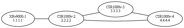
Interesting! We could draw the network graph by just using XRv9000-1 Router IS-IS Link State Database information.
This is the true difference of Link-State Protocols (OSPF and IS-IS) compared to Distance Vectors (Such as EIGRP and RIP).
Distance Vector Routing Protocols
Distance Vector Routing Protocols DO NOT know about the entire network topology.
A router is just learning the routes from it’s neighbors, in other words they just know whatever their neighbors tell them, and the neighbor will be considered as the next-hop in order to reach to those routes.
Sometimes this behavior is called: Rumor Based route learning.
RIP, IGRP and EIGRP are Distance Vector routing protocols. RIP is using the simple Bellman-Ford algorithm to do the path calculation and it is considering the Hop count, but on the other hand EIGRP uses DUAL (Diffusing Update Algorithm) and Composite metric in order to do the path calculation.
In addition to that, EIGRP is using some mathematical condition which is called FC (Feasibility Condition) to find the Loop Free neighbors for a specific prefix.
This are making the EIGRP to be an Advanced Distance Vector Protocol.
NOTE: Some people mentioning that EIGRP is a Hybrid Protocol, but it is not true at some point, because the Hybrid means: EIGRP is inheriting the Link-State and Distance Vector protocol behaviors at the same time, but you can easily realize that EIGRP has no idea about Link-State Topological database. Better to name it: An Advanced Distance Vector Protocol.
Let’s configure and examine a simle EIGRP on the above topology:
XRv9000-1:
router eigrp SME
 address-family ipv4
  autonomous-system 1
  interface Loopback0
  !
  interface GigabitEthernet0/0/0/1
  !
 !
!


All IOS-XE routers:
router eigrp SME
 !
 address-family ipv4 unicast autonomous-system 1
  !
  topology base
  exit-af-topology
  network 0.0.0.0
 exit-address-family
!
The output of EIGRP Topology Database: (It is not the same as OSPF or IS-IS LSDB!):
RP/0/RP0/CPU0:XRv9000-1(config)#do sh eigrp ipv4 topology all-links
Thu Apr 14 15:25:31.894 UTC

IPv4-EIGRP VR(SME) Topology Table for AS(1)/ID(1.1.1.1)

Codes: P - Passive, A - Active, U - Update, Q - Query, R - Reply,
       r - reply Status, s - sia Status

P 1.1.1.1/32, 1 successors, FD is 131072, RIB is 1024, serno 1
        via Connected, Loopback0
P 1.2.0.0/24, 1 successors, FD is 1310720, RIB is 10240, serno 2
        via Connected, GigabitEthernet0/0/0/1
P 2.2.2.2/32, 1 successors, FD is 1392640, RIB is 10880, serno 8
        via 1.2.0.2 (1392640/163840), GigabitEthernet0/0/0/1
P 2.3.0.0/24, 1 successors, FD is 1966080, RIB is 15360, serno 7
        via 1.2.0.2 (1966080/1310720), GigabitEthernet0/0/0/1
P 2.4.0.0/24, 1 successors, FD is 1966080, RIB is 15360, serno 6
        via 1.2.0.2 (1966080/1310720), GigabitEthernet0/0/0/1
P 3.3.3.3/32, 1 successors, FD is 2048000, RIB is 16000, serno 5
        via 1.2.0.2 (2048000/1392640), GigabitEthernet0/0/0/1
P 3.4.0.0/24, 1 successors, FD is 2621440, RIB is 20480, serno 4
        via 1.2.0.2 (2621440/1966080), GigabitEthernet0/0/0/1
P 4.4.4.4/32, 1 successors, FD is 2048000, RIB is 16000, serno 3
        via 1.2.0.2 (2048000/1392640), GigabitEthernet0/0/0/1
XRv9000v only knows whatever it’s next-hop (Router 2) tells it! that is it.
In which cases we should use a Link State Protocol (The only choice)?
- With many technologies which strictly need the Topological view of the network such as: MPLS-TE with RSVP, Segment-Routing and SR-TE, Optimal Route-Reflection (ORR)
- Fast Reroute with Remote-LFA and SR TI-LFA

1 Comment