
we’ve come from the previous page here…
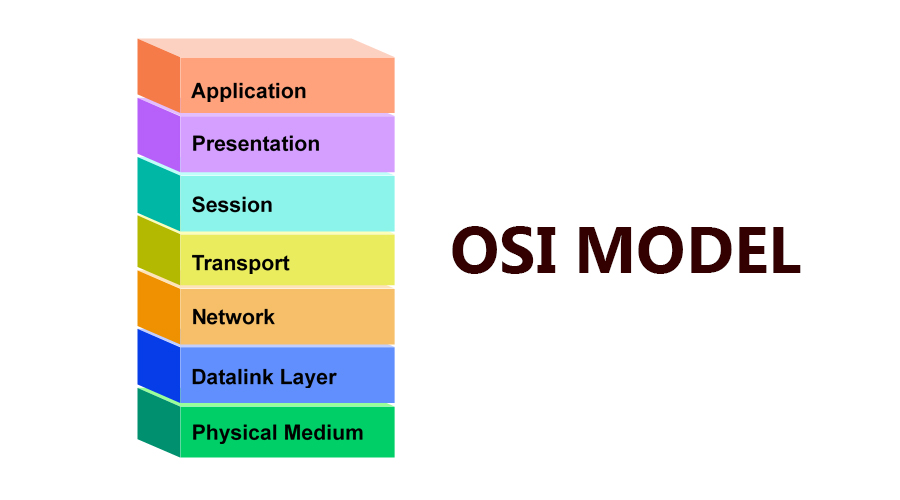
ISO/OSI Model; Open Systems Interconnection
‘N’ Notation
There are many terminologies that are used to describe the OSI Model and its layers, one such terminology is the N Notation.
The letter N is often used to generically refer to ta number within the computer world.
In the OSI Reference Model, each layer is numbered from 1 to 7. Suppose you are talking about the transport layer i.e the 4th layer of the Model. In N Notation form this layer will be the Nth layer and the layer above and below it will be called (N+1) and (N-1) layer.
If you are looking at the network layer (layer 3), then the N+3 layer is the presentation layer (layer 6).
Britannica published the concept of the protocol as follows
protocol, in computer science, a set of rules or procedures for transmitting data between electronic devices, such as computers. In order for computers to exchange information, there must be a preexisting agreement as to how the information will be structured and how each side will send and receive it. Without a protocol, a transmitting computer, for example, could be sending its data in 8-bit packets while the receiving computer might expect the data in 16-bit packets. Protocols are established by international or industrywide organizations. Perhaps the most important computer protocol is OSI (Open Systems Interconnection), a set of guidelines for implementing networking communications between computers. Among the most important sets of Internet protocols are TCP/IP (Transmission Control Protocol/Internet Protocol), HTTPS (Secure HyperText Transmission Protocol), SMTP (Simple Mail Transfer Protocol), and DNS (Domain Name System).
Data Units (PDUs) And Service Data Units (SDUs)
A PDU stands for Protocol Data Unit is a complete message that has been implemented by the Nth layer protocol. This PDU is then passed to layer N-1, and it becomes the data for that layer and gives its service to the data. Thus, the layer N’s Protocol Data Unit means PDU is called layer N-1’s Service Data Unit i.e SDU.
Previous
Next
Encapsulation
This process of passing PDU’s and the next layers takes it as SDU’s is called data encapsulation. Encapsulation is wrapping up of data and each higher layer of data of the model is wrapped by the next lower layer. The process reverses when the data travels from the lower layer to the higher layer and the wrapping is removed by each layer.
Basically, encapsulation means that the particular layer “adding” protocol information to the next layer, from Layer 7 straight down to Layer 1 in purpose of transmitting data from one device to another device correctly. There also term decapsulation and surely you know what it means: unwrap the frame so the device able to read the data.
Previous
Next
Seven layers of the OSI Reference Model
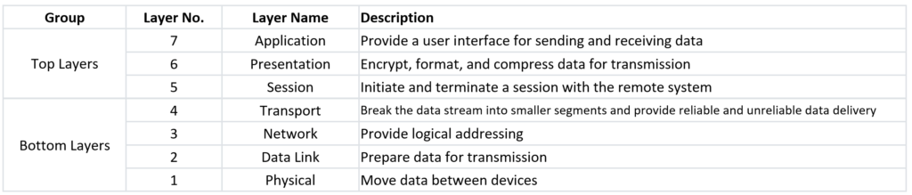
Application Layer
The seventh layer of the OSI model is called the application layer. As the name suggests, it deals with software and applications that run on our computers, such as the web browser you’re using to read this web page. Basically, this layer interacts with end-users through those apps and provides an interface between them and the underlying network connections.
Application layer functions
Transport access and management
It allows a user to access, retrieve and manage files in a remote computer.
It provides the basis for email forwarding and storage facilities.
For various reasons, it can be said that the standardization of terminals has completely failed. The OSI solution to this problem is to define a virtual terminal that is really just an abstract data structure that takes the abstract state of the actual terminal. This abstract data structure can be operated by both the keyboard and the computer and reflects the current state of the data structure on the display. The computer can query this abstract data structure and change this abstract data structure so that the output appears on the screen.
In addition to the three functions above, there are some other functions: directory services, remote job entry, graphics, information communication and so on.
Application layer Protocols
- SOAP, Simple Object Access Protocol
- Simple Service Discovery Protocol, A discovery protocol employed by UPnP
- TCAP, Transaction Capabilities Application Part
- Universal Plug and Play
- DHCP
- DNS Domain Name System
- BOOTP Bootstrap Protocol
- HTTP
- HTTPS
- NFS
- POP3
- SMTP
- SNMP
- FTP
- NTP
- IRC
- Telnet
- SSH
- TFTP
- IMAP
- Gemini
Different kind of Application Programs
There are two types of application programs: Network-aware and Network-unaware. An application program is considered a Network-aware application if it can make any type of network request. If an application program cannot make any type of network request, it is considered a Network-unaware program.
Network-aware programs are further divided into two types.
- Programs that are mainly built to work on a local system. This type of program occasionally accesses the network for particular reasons such as updates, documentation, and troubleshooting. MS-Word, Adobe-Photoshop, and VLC Player are examples of this type of program.
- Programs that are mainly built to work with a remote system. This type of program provides a platform to access resources available on a remote system. This type of program only works if the system is connected to the network. SSH, FTP, and TFTP are examples of this type of program.
Presentation Layer
This layer is primarily responsible for preparing data so that it can be used by the application layer; in other words, layer 6 makes the data presentable for applications to consume. The presentation layer is responsible for translation, encryption, and compression of data.
Two communicating devices communicating may be using different encoding methods, so layer 6 is responsible for translating incoming data into a syntax that the application layer of the receiving device can understand.
If the devices are communicating over an encrypted connection, layer 6 is responsible for adding the encryption on the sender’s end as well as decoding the encryption on the receiver’s end so that it can present the application layer with unencrypted, readable data.
Finally, the presentation layer is also responsible for compressing data it receives from the application layer before delivering it to layer 5. This helps improve the speed and efficiency of communication by minimizing the amount of data that will be transferred.
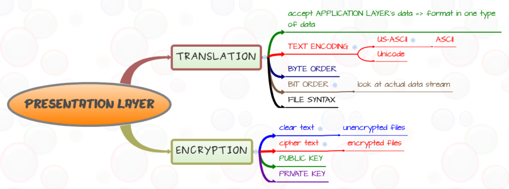
Presentation Layer Functions
Encoding (for example, ASCII encoding),
Encryption (like when applying SSL/TLS), and
Compression (such as by using gzip).
Presentation Protocols
- TLS Transport Layer Security
- AFP Apple Filing Protocol
- eXternal Data Representation (XDR)
- Independent Computing Architecture (ICA), the Citrix system core protocol
- Lightweight Presentation Protocol (LPP)
- 25 Packet Assembler/Disassembler Protocol (PAD)
- NetWare Core Protocol (NCP)
- Network Data Representation (NDR)
- Tox, The Tox protocol is sometimes regarded as part of both the presentation and application layer
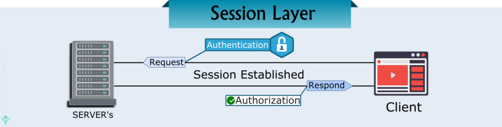
Session Layer
The session layer is the fifth layer of the OSI model. It is responsible for setting up, managing, and dismantling sessions between presentation layer entities and providing dialogs between computers.
When an application makes a network request, this layer checks whether the requested resource is available on the local system or on a remote system. If the requested resource is available on a remote system, it tests whether a network connection to access that resource is available or not. If a network connection is not available, it sends an error message back to the application informing that the connection is not available.
If a network connection is available, it establishes a session with the remote system. For each request, it uses a separate session. This allows multiple applications to send or receive data simultaneously. When data transmission is completed, it terminates the session.
Session Layer Function
- Establish a connection between the session entities
In order to establish a session connection for two peer session service users, several things should be done as follows.
- Map the session address to the shipping address.
- Select the required transport quality of service (QOS) parameters.
- Negotiate the session parameters.
- Identify each session connection.
- Transmit limited transparent user data.
- Data transfer phase.
This stage is to realize the organized and synchronous data transmission between two session users, where the user data unit is the SSDU and the protocol data unit is the SPDU, and the data transmission between the session users is performed by converting the SSDU into the SPDU.
- Connection release
Connection release is through the “ordered release”, “discarded”, “limited transparent user data transfer” and other functional units to release the session connection.
Session-Level Standards In order to enable functional negotiation during the session establishment phase and to facilitate reference and reference by other international standards, twelve functional units are defined. Each system can be based on its own circumstances and needs, based on the core functional service unit, matching other functional units to form a reasonable subset of session services.
Session Layer Protocols
- TLS – Transport Layer Security (RFC 8446)
- 9P Distributed file system protocol developed originally as part of Plan 9
- ADSP AppleTalk Data Stream Protocol
- ASP AppleTalk Session Protocol
- 245 Call Control Protocol for Multimedia Communications
- iSNS Internet Storage Name Service
- NetBIOS, File Sharing and Name Resolution protocol – the basis of file sharing with Windows.
- NetBEUI, NetBIOS Enhanced User Interface
- NCP NetWare Core Protocol
- PAP Printer Access Protocol
- RPC Remote Procedure Call
- RTCP RTP Control Protocol
- SDP Sockets Direct Protocol
- SMB Server Message Block
- SMPP Short Message Peer-to-Peer
- SOCKS “SOCKetS”
- ZIP Zone Information Protocol {For AppleTalk}
Transport Layer
Layer 4 is responsible for end-to-end communication between the two devices. The protocol data unit (PDU) at this layer is a segment before sending it to layer 3. The original data is broken up into chunks called segments and sent over multiple pathways to gain some efficiency (by avoiding congestion). It also incorporates security since the segments are scattered and makes it harder for an attacker to read the entire message. On the receiving device, the transport layer is responsible for reassembling these segments in the correct order before sending it over to the session layer. Each segment contains header information such as source port, assigned based on availability by the client (sender’s) operating system, destination port, sequence and acknowledgment numbers that communicate which segment was delivered and what it expects to receive next. The delivery can either be reliable or unreliable and based on that, the protocols used are TCP or UDP.In case of a reliable connection (TCP), error control checks are in place that the determine if the message received is complete. If not, it asks the message to be resent. Transmission failures due to differences in connection speeds might occur. Flow control is used so that a sender with a faster connection doesn’t end up overwhelming a receiver with a slow connection. The transport layer also includes multiplexing and demultiplexing to enable clients to communicate with different application processes in one session.So, what happens in UDP? Let’s take a trip down memory lane and go back to your eighth-grade math class (or any lecture that you can recall). That’s an example of unreliable delivery. Since the teacher delivering the lecture (i.e., the data transmitted) didn’t wait for an acknowledgment from students confirming that the message was delivered in its entirety, it’s a UDP transmission. UDP is used when the size of the file is massive, like in audio or video transmissions, and it is time sensitive. For instance, you wouldn’t want a time lag after every frame in a video.
Transport Layer Functions
- Connection-Oriented Communication: Devices at the end-points of a network communication establish a handshake protocol to ensure a connection is robust before data is exchanged. The weakness of this method is that for each delivered message, there is a requirement for an acknowledgment, adding considerable network load compared to self-error-correcting packets. The repeated requests cause significant slowdown of network speed when defective byte streams or datagrams are sent.
- Same Order Delivery: Ensures that packets are always delivered in strict sequence. Although the network layer is responsible, the transport layer can fix any discrepancies in sequence caused by packet drops or device interruption.
- Data Integrity: Using checksums, the data integrity across all the delivery layers can be ensured. These checksums guarantee that the data transmitted is the same as the data received through repeated attempts made by other layers to have missing data resent.
- Flow Control: Devices at each end of a network connection often have no way of knowing each other’s capabilities in terms of data throughput and can therefore send data faster than the receiving device is able to buffer or process it. In these cases, buffer overruns can cause complete communication breakdowns. Conversely, if the receiving device is not receiving data fast enough, this causes a buffer underrun, which may well cause an unnecessary reduction in network performance.
- Traffic Control: Digital communications networks are subject to bandwidth and processing speed restrictions, which can mean a huge amount of potential for data congestion on the network. This network congestion can affect almost every part of a network. The transport layer can identify the symptoms of overloaded nodes and reduced flow rates.
- Multiplexing: The transmission of multiple packet streams from unrelated applications or other sources (multiplexing) across a network requires some very dedicated control mechanisms, which are found in the transport layer. This multiplexing allows the use of simultaneous applications over a network such as when different internet browsers are opened on the same computer. In the OSI model, multiplexing is handled in the service layer.
- Byte orientation: Some applications prefer to receive byte streams instead of packets; the transport layer allows for the transmission of byte-oriented data streams if required.
Transport Layer Protocols
- TCP Transmission Control Protocol
- UDP User Datagram Protocol
- AEP AppleTalk Echo Protocol
- AH Authentication Header over IP or IPSec
- DCCP Datagram Congestion Control Protocol
- ESP Encapsulating Security Payload over IP or IPSec
- FCP Fibre Channel Protocol
- NetBIOS NetBIOS, File Sharing and Name Resolution
- IL Originally developed as transport layer for 9P
- iSCSI Internet Small Computer System Interface
- NBF NetBIOS Frames protocol
- SCTP Stream Control Transmission Protocol
- Sinec H1 for telecontrol
- TUP, Telephone User Part
- SPX Sequenced Packet Exchange
- NBP Name Binding Protocol {for AppleTalk}
- QUIC
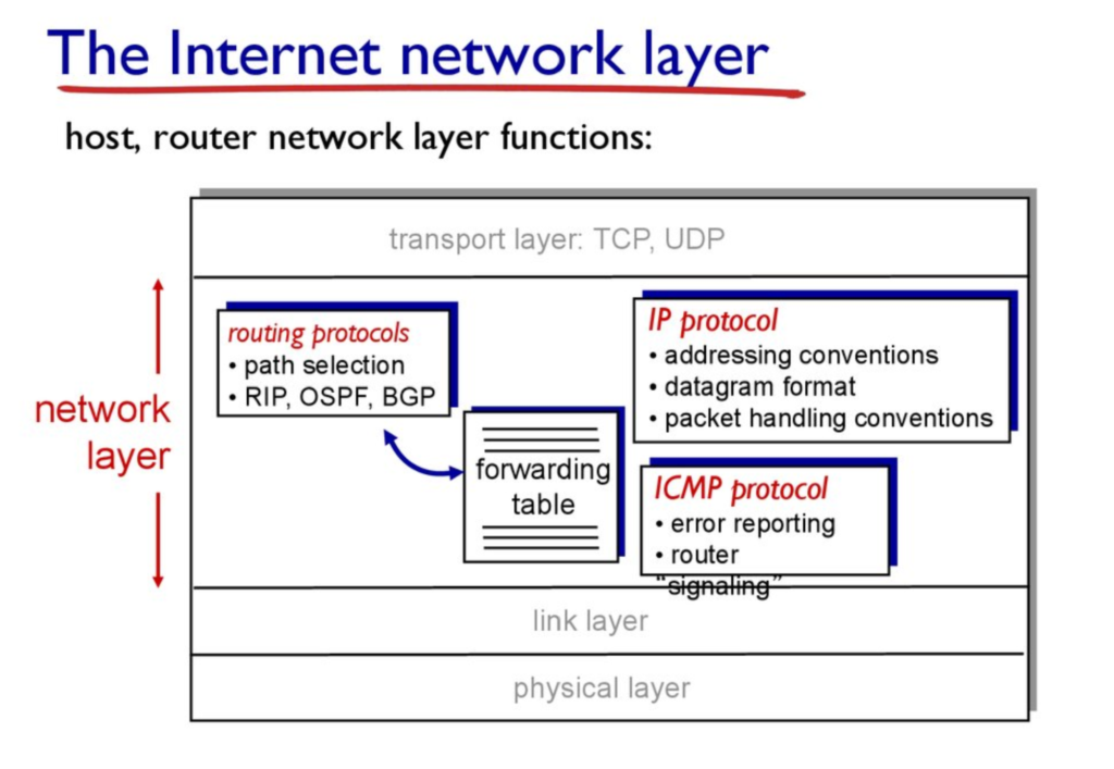
Network Layer
The Network Layer’s main objective is to move data. In converts logical address to physical address, and takes the shortest path to the receiver. Layer 3 of the OSI model routes the data along multiple pathways. The PDU for this OSI layer is referred to as a packet. It contains information such as source and destination IP addresses to identify end devices. The most commonly used protocol at this layer is IPv4.
The network layer is responsible for facilitating data transfer between two different networks. If the two devices communicating are on the same network, then the network layer is unnecessary. The network layer breaks up segments from the transport layer into smaller units, called packets, on the sender’s device, and reassembling these packets on the receiving device. The network layer also finds the best physical path for the data to reach its destination; this is known as routing.
Network Layer Function
- Routing packets from source to destination (host-to-host delivery) across different networks,
- Translating logical addresses into physical addresses, and
- Fragmenting packets into smaller pieces to allow it to travel across links with lower maximum transmission units (MTU).
Network Layer Protocols
- IP Internet Protocol
- ICMP Internet Control Message Protocol
- ARP Address Resolution Protocol
- CLNP Connectionless Networking Protocol
- IPX Internetwork Packet Exchange
- NAT Network Address Translation
- Routed-SMLT
- SCCP Signalling Connection Control Part
- AppleTalk DDP
- HSRP Hot Standby Router protocol
- VRRP Virtual Router Redundancy Protocol
- RIP Routing Information Protocol (v1 and v2)
- OSPF Open Shortest Path First (v1 and v2)
- IPSEC IPsec
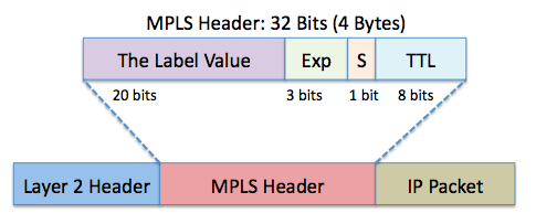
Layer 2.5 – MPLS
MPLS stands for Multiprotocol Label Switching. This layer is in between the Data Link Layer and the Network layer. It is not really part of the OSI model but aids in describing the operation of MPLS. MPLS modifies the Data Link layer frame with labels to aid in routing the data. Multiprotocol Label Switching (MPLS) is used in telecommunications networks that directs data from one network node to the next based on short path labels rather than long network addresses. This simplifies the lookups in the routing table. The labels identify virtual links (paths) between distant nodes rather than endpoints. MPLS can encapsulate packets of various network protocols including legacy protocols such as T1/E1, ATM, Frame Relay, and DSL. MPLS is used to connect Service Providers to Service Providers and to connect LANs through virtual cloud WANs together. Packet-forwarding decisions are made solely on the contents of this label, without the need to examine the packet itself. This allows one to create end-to-end circuits across any type of transport medium, using any protocol. The primary benefit is to eliminate dependence on a particular OSI model data link layer . It was designed to provide a unified data-carrying service for both circuit-based clients and packet-switching clients which provide a datagram service model.
Data-Link Layer
The data link layer or layer 2 is the second layer of the seven-layer OSI model of computer networking. This layer is the protocol layer that transfers data between adjacent network nodes in a wide area network (WAN) or between nodes on the same local area network (LAN) segment. The data link layer provides the functional and procedural means to transfer data between network entities and might provide the means to detect and possibly correct errors that may occur in the physical layer.
The data link layer is concerned with local delivery of frames between devices on the same LAN. Data-link frames, as these protocol data units are called, do not cross the boundaries of a local network. Inter-network routing and global addressing are higher-layer functions, allowing data-link protocols to focus on local delivery, addressing, and media arbitration. This way, the data link layer is analogous to a neighborhood traffic cop; it endeavors to arbitrate between parties contending for access to a medium, without concern for their ultimate destination. When devices attempt to use a medium simultaneously, frame collisions occur. Data-link protocols specify how devices detect and recover from such collisions, and may provide mechanisms to reduce or prevent them.
Examples of data link protocols are Ethernet for local area networks (multi-node), the Point-to-Point Protocol (PPP), HDLC and ADCCP for point-to-point (dual-node) connections. In the Internet Protocol Suite (TCP/IP), the data link layer functionality is contained within the link layer, the lowest layer of the descriptive model.
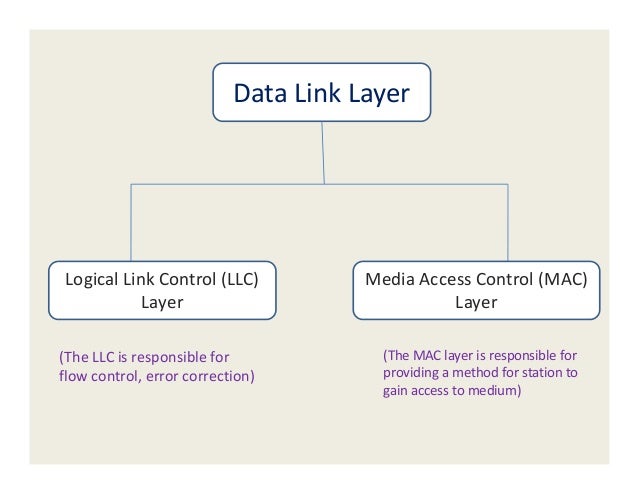
The data link layer has two sublayers:
Logical Link Control (LLC) layer (the upper sublayer)
The LLC sublayer assists with multiplexing and de-multiplexing over the MAC layer. It takes the packet from the network layer and adds control information to deliver it to right destination (hop-to-hop flow and error control).
Media Access Control (MAC) layer (the lower sublayer)
The MAC sublayer interacts directly with the physical layer and deals with framing/de-framing, typically done by NIC cards on PCs. It is also responsible for collision resolution on shared or broadcast links where multiple end nodes connect to the same link.
Data-Link Layers Function
- Framing
- L2 Addressing
- Error Control
- Flow Control
- Access Control
Data-Link Layer Protocols
- Ethernet
- VTP VLAN Trunking Protocol
- VLAN Virtual Local Area Network
- ARCnet Attached Resource Computer NETwork
- ARP Address Resolution Protocol
- ATM Asynchronous Transfer Mode
- CHAP Challenge Handshake Authentication Protocol
- CDP Cisco Discovery Protocol
- DCAP Data Link Switching Client Access Protocol
- Distributed Multi-Link Trunking
- Distributed Split Multi-Link Trunking
- DTP Dynamic Trunking Protocol
- Econet
- FDDI Fiber Distributed Data Interface
- Frame Relay
- ITU-T G.hn Data Link Layer
- HDLC High-Level Data Link Control
- IEEE 802.11 WiFi
- IEEE 802.16 WiMAX
- LACP Link Aggregation Control Protocol
- LattisNet
- LocalTalk
- L2F Layer 2 Forwarding Protocol
- L2TP Layer 2 Tunneling Protocol
- LLDP Link Layer Discovery Protocol
- LLDP-MED Link Layer Discovery Protocol – Media Endpoint Discovery
- MAC Media Access Control
- 710 Simplified Message Transfer Part
- Multi-link trunking Protocol
- NDP Neighbor Discovery Protocol
- PAgP – Cisco Systems proprietary link aggregation protocol
- PPP Point-to-Point Protocol
- PPTP Point-to-Point Tunneling Protocol
- PAP Password Authentication Protocol
- RPR IEEE 802.17 Resilient Packet Ring
- SLIP Serial Line Internet Protocol (obsolete)
- StarLAN
- Space Data Link Protocol, one of the norms for Space Data Link from the Consultative Committee for Space Data Systems
- STP Spanning Tree Protocol
- Split multi-link trunking Protocol
- Token Ring a protocol developed by IBM; the name can also be used to describe the token passing ring logical topology that it popularized.
- Virtual Extended Network (VEN) a protocol developed by iQuila.
Physical Layer
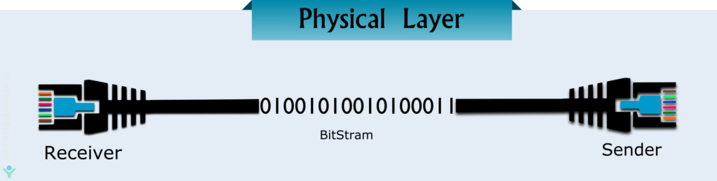
The physical layer is the lowest layer of the OSI model. This layer controls the way unstructured, raw, bit -stream data is sent and received over a physical medium. This layer is composed of the electrical, optical, and physical components of the network. The physical layer carries the signals for all of the higher layers.
This layer plays with most of the network’s physical connections – wireless transmission, cabling, cabling standards and types, connectors and types, network interface cards, and more – as per network requirements. However, the physical layer does not deal with the actual physical medium (like copper, fiber). The physical layer sometimes plays an important role in the effective sharing of available communication resources, and helps avoid contention among multiple users. It also handles the transmission rate to improve the flow of data between a sender and receiver. The Physical Layer mainly defines standards for media and devices that are used to move data across the network. 10BaseT, 10Base100, CSU/DSU, DCE, and DTE are examples of the standards used in this layer.
Physical Layer Functions
The physical layer provides the following services:
- Modulates the process of converting a signal from one form to another so that it can be physically transmitted over a communication channel
- Bit-by-bit delivery
- Line coding, which allows data to be sent by hardware devices that are optimized for digital communications that may have discreet timing on the transmission link
- Bit synchronization for synchronous serial communications
- Start-stop signaling and flow control in asynchronous serial communication
- Circuit switching and multiplexing hardware control of multiplexed digital signals
- Carrier sensing and collision detection, whereby the physical layer detects carrier availability and avoids the congestion problems caused by undeliverable packets
- Signal equalization to ensure reliable connections and facilitate multiplexing
- Forward error correction/channel coding such as error correction code
- Bit interleaving to improve error correction
- Auto-negotiation
- Transmission mode control
Physical Layer Protocols
- Telephone network modems
- IrDA physical layer
- USB physical layer – Universal Serial Bus
- EIA RS-232, EIA-422, EIA-423, RS-449, RS-485
- Ethernet physical layer 10BASE-T, 10BASE2, 10BASE5, 100BASE-TX, 100BASE-FX, 1000BASE-T, 1000BASE-SX and other varieties
- Varieties of 802.11 Wi-Fi physical layers
- DSL – Digital Subscriber Line
- ISDN – Integrated Services Digital Network
- T1 and other T-carrier links, and E1 and other E-carrier links
- ITU Recommendations: see ITU-T
- IEEE 1394 interfaces
- TransferJet
- Etherloop
- ARINC 818 Avionics Digital Video Bus
- hn/G.9960 physical layer
- CAN bus (controller area network) physical layer
- Mobile Industry Processor Interface physical layer
- Infrared – Infrared Data Association
- Frame Relay
- FO Fiber optics
- X.25
How Is the World Connected?
The short answer is via cables. It might be interesting to understand the physical communication channels through which data flows, how they are built, who owns them and gain a general overview of how these channels that connect the entire planet came into existence.
What happens in the background when you’re trying to send an image file to your friend? It gets transformed into 1s and 0s (binary) that are transported using radio waves to the router. This gets done by using frequency modulation where a certain frequency is used to represent 1s and another to signify 0s. So long as the receiver knows which frequency is used to represent the 1s and 0s, they can read the signal.
The information then leaves the router via cables in the form of light or electricity, depending upon the wire’s material. These cables are typically set up and owned by internet service providers (ISPs). The ISPs are responsible for determining the most efficient route that the message can take to reach its next location, an internet hub. The internet hub is where multiple ISPs, telecommunication companies, and internet operators exchange traffic.
When it comes to long-distance communication, primarily, it is the submarine cable providers who step in to lay down undersea cables. Data travels across oceans and continents using these cables. However, not everyone has access to the internet. In sparsely populated or low-income areas, the return on investment is inadequate for providers who bear the cost of setting up the infrastructure.
In Conclusion
The OSI layers can be mapped to the four-layered TCP/IP model (that came before it). This tells us that rather than being a strict network implementation model, it’s a framework or a guideline that gives us a clearer picture of what goes on when machines from across the world or in the same network communicate with each other.
Hopefully, going over the OSI model with its different network layers has helped you gain a fair understanding of how data moves at the level of bits and signals and how we, as end-users, interact with it at the application level.
