
A Brief Evolution of Spanning-Tree Protocols on NX-OS
Before discussing on IEEE 802.1w, I would want to present a brief history of Spanning-tree evolution, the we continue with our main subject of this post.
Spanning-tree is the loop prevention mechanism in Layer-2. According to graph theory:
- Spanning: A spanning graph is a subgraph obtained by only edge deletions. In other words, the subgraph’s vertex set is the original graph’s entire vertex set.
- Tree: A tree is a connected acyclic graph. (acyclic means no cycle).
In order for a graph with n vertices to be loop-free, we have to have n-1 edges. STP logically blocks physical loops in a Layer 2 network, preventing frames from circling the network forever.
Amongst thousands of proposals for Layer-2 loop prevention and few Spanning-Tree Protocols which were implemented in industry, I will summary the ones supported on NX-OS below:
- Rapid PVST+:
- IEEE 802.1w is not a timer-based protocol
- BPDU version: 2
- The destination MAC address of the BPDU is 01:80:c2:00:00:00
- Multiple Spanning Tree Protocol (MSTP): IEEE 802.1s inspired by the earlier Cisco proprietary MISTP implementation
- BPDU Version: 3
- RSTP runs behind the scene
- Cisco implementation of MSTP provides up to 16 instances of RSTP and combines many VLANs
IEEE 802.1w (RSTP)
In order to improve the convergence time of STP (or CST), IEEE released IEEE 802.1w standard. With this standard root bridge election and patch calculation remain the same as those with CST. As opposed to IEEE 802.1D wherein only root bridge sends BPDU, with 802.1w, each switch sends its own BPDU. RSTP BPDUs therefore become more similar to a Hello mechanism known from routing protocols. A switch in this standard can detect a neighbor failure in only three hello intervals, versus (20s default) Max-age timer for IEEE 802.1D. If a switch ceases to receive RSTP BPDUs on its port, it is certain that the problem is contained on the link between this switch and its neighbor.
RSTP Port States
Here are the port states:
- Discarding:
- The switchport is enabled, but the port is not forwarding any traffic.
- This state combines the traditional STP states: disabled, blocking, and listening
- Learning: The switch still does not forward any other network traffic besides BPDUs. It learns incoming frames source MAC addresses
- Forwarding: This is the final state for a switch port to forward network traffic.

RSTP Port Roles
Root ports and designated ports are the same for both STP and RSTP. However, there are two RSTP port roles that correspond to the blocking state of STP. In STP, a blocked port is defined as not being the designated or root port. RSTP has two port roles for this purpose.
- Root Port: Same as with STP, this is the non-root switch’s best path to the root
- Alternate Port: Replaces the root port when the root port fails
- That is why Cisco proprietary UplinkFast is obsolete with IEEE 802.1w
- Designated Port: Same as with STP
- Backup Port: Replaces designated port when a designated port fails. The backup port is a backup to a shared medium, such as a hub. A backup port is less common because hubs are now considered legacy devices.

RSTP Port Types
- Network port: Any full duplex port that connects to another RSTP switch and becomes a designated port.
- Edge ports: This is equivalent of PortFast feature with STP. An Edge Port immediately becomes Designated Forwarding after coming up. It still sends BPDUs, but it expects not to receive any. Should a BPDU be received by an Edge port, this port will revert to the Non-Edge type and start operating as a common RSTP port. We have two flavors of edge ports.
- Edge port
- Edge trunk port: Typically used between ESXi and Nexus Switch. You must also use edge port trunk to connect to UCS series servers.
- Normal ports: Any port which don’t fall under the above ports.
Edge port Configuration:
! To configure all switchports as edge ports.
N9K01# configure terminal
N9K01(config)# spanning-tree port type edge default
! To configure one switchport as an edge port.
N9K01# configure terminal
N9K01(config)# interface ethernet 1/1
N9K01(config-if)# spanning-tree port type edge
! To configure one switchport as an edge trunk port.
N9K01# configure terminal
N9K01(config)# interface ethernet 1/1
N9K01(config-if)# spanning-tree port type edge trunk
Network Port Configuration:
! To configure all switchports as network ports.
N9K01# configure terminal
N9K01(config)# spanning-tree port type network default
! To configure one switchport as an network port.
N9K01# configure terminal
N9K01(config)# interface ethernet 1/1
N9K01(config-if)# spanning-tree port type network
Building the Topology with IEEE 802.1w
The end topology result is exactly the same as the one calculated by 802.1D. However, how to form that topology rapidly has changed.
- Once two switches connect to each other, they verify that they are connected with a network port by checking the full-duplex status. They both put their ports in designated blocking state (Yes, RSTP decoupled the port role from their state, hence we have designated in blocking state with RSTP).
- They establish a handshake with each other to advertise a proposal (in configuration BPDUs) that their interface should be the DP for that port.
- There can be only one DP per segment, so each switch identifies whether it is the superior or inferior switch, using the same logic as in 802.1D for the system identifier.
- The inferior switch (SW2) recognizes that it is inferior and marks its local port (e1/2) as the RP. At that same time, it moves all non-edge ports to a discarding state.
- The inferior switch (SW2) sends an agreement (configuration BPDU) to the root bridge (SW1), which signifies to the root bridge that synchronization is occurring on that switch. With that it explicitly authorizes the root bridge to put its port in the forwarding state.
- The superior switch moves its DP (e1/1) to a forwarding state. The inferior switch (SW2) moves its RP (e1/2) to a forwarding state too.
- The inferior switch (SW2) repeats the process for any downstream switches connected to it.
- With blocking the downstream ports, you cannot have a loop.

Workshop
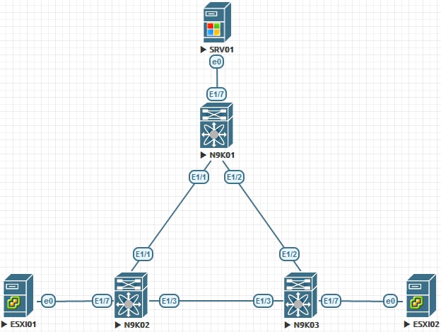
In the workshop below, I am trying to show you the different port types with RSTP. I am going to configure the N9K02 and N9K03 E1/7s as spanning-tree port type edge trunk, whereas the E1/7 on N9K01 would be spanning-tree port type edge. I will also configure the inter-switch ports (point-to-point ports) with the port type of network with spanning-tree port type network (which is the default)
N9K01:
  configure terminal
    interface ethernet 1/1-2
      spanning-tree port type network
    switchport mode trunk
    exit
    interface ethernet 1/7
      spanning-tree port type edge
    switchport mode access
    switchport access vlan 100
    exit
N9K02:
  configure terminal
    interface ethernet 1/1 , ethernet 1/3
      spanning-tree port type network
    switchport mode trunk
    exit
    interface ethernet 1/7
      spanning-tree port type edge trunk
    switchport mode trunk
  exit
N9K03:
  configure terminal
    interface ethernet 1/2 , ethernet 1/3
      spanning-tree port type network
    switchport mode trunk
    exit
    interface ethernet 1/7
      spanning-tree port type edge trunk
    switchport mode trunk
    exit
Verification
N9K01:
N9K01(config)# show interface ethernet 1/1 switchport
Name: Ethernet1/1
  Switchport: Enabled
  Switchport Monitor: Not enabled
  Switchport Isolated : Not enabled
  Switchport Block Multicast: Not enabled
  Switchport Block Unicast: Not enabled
  Operational Mode: trunk
  Access Mode VLAN: 1 (default)
  Trunking Native Mode VLAN: 1 (default)
  Trunking VLANs Allowed: 1-4094
  Voice VLAN: none


N9K01(config)# show interface ethernet 1/7 switchport
Name: Ethernet1/7
  Switchport: Enabled
  Switchport Monitor: Not enabled
  Switchport Isolated : Not enabled
  Switchport Block Multicast: Not enabled
  Switchport Block Unicast: Not enabled
  Operational Mode: access
  Access Mode VLAN: 100 (VLAN0100)
  Trunking Native Mode VLAN: 1 (default)
  Trunking VLANs Allowed: 1-4094
  Voice VLAN: none
N9K03
N9K03(config)# show interface ethernet 1/7 switchport
Name: Ethernet1/7
  Switchport: Enabled
  Switchport Monitor: Not enabled
  Switchport Isolated : Not enabled
  Switchport Block Multicast: Not enabled
  Switchport Block Unicast: Not enabled
  Operational Mode: trunk
  Access Mode VLAN: 1 (default)
  Trunking Native Mode VLAN: 1 (default)
  Trunking VLANs Allowed: 1-4094
  Voice VLAN: none
1 Comment