vPC and STP
By default, only vPC primary switch (Verify it using show vpc role) sends and receives BPDUs on the member ports (even if the root bridge is the vPC secondary switch. Verify it yourself by show spanning-tree interface pomember detail | i sent on the secondary switch). Let’s imagine that primary devices goes down, then the downstream switch does not receive any BPDU, then we will experience couple of seconds for the RSTP to converge.
The command peer-switch under vpc domain configuration allows vPC peers to appear as a single STP root with the same bridge ID. Note that you must issue this command on both peers to become operational. With this feature enabled, both switches then receive and send BPDUs.
Another note that, orphan ports receive the BPDUs of connected switch not with the vPC bridge ID.
! The following commands must be consistent across both switches
switch(config)# vpc domain 1
switch(config-vpc-domain)# peer-switch
switch(config-vpc-domain)# exit
! Strongly recommends define the vPC domain as STP root for all VLANs
switch(config)# spanning-tree vlan 1-3967 priority 4096
vPC and Bridge Assurance
Do you remember Bridge Assurance? Should you need a refresher, here is the post we talked about it. However, as far as vPC concerns, Cisco strongly recommends Bridge Assurance on peer-link. Once you create the peer-link, You are getting a syslog message that Bridge Assurance enables for you on the link:
switch(config)# int po1
switch(config-if)# switchport
switch(config-if)# switchport mode trunk
switch(config-if)# vpc peer-link
2022 May 15 03:16:33 switch %$ VDC-1 %$ %STP-2-BRIDGE_ASS
URANCE_WARNING: Bridge Assurance MUST be enabled at the remotely connected interface
switch(config-if)# 2022 May 15 03:16:39 switch %$ VDC-1 %$ stp: Please note that spanning tree port type is changed to "network" port type on vPC peer-link. This will enable spanning tree Bridge Assurance on vPC peer-link provided the STP Bridge Assurance (which is enabled  by default) is not disabled.
vPC and FHRP
vPC switches are typically the boundary between L2 (towards the servers) and L3 (towards the spines). Well, we have our Layer 2 redundancy by using vPC, but there is no so far redundancy at the L3 for servers gateway. So, we typically run FHRP on vPC peers.

- Control plane perceives HSRP/VRRP active/standby or master/backup role
- Active/Master has the vMAC
- Standby relays the ARP requests to active/master via peer-link
- Data plane operates in Active/Active.
- The server sees the vPC peer as a single switch in Layer 2 via it’s PO1
- The server sends ARP request to the primary switch based on hashing algorithm:
- vPC primary replies to ARP request with vMAC directly to the server.
- The server gets the MAC address and forwards the traffic over the link towards the secondary switch.
- The server sends ARP request to the secondary switch based on hashing algorithm:
- vPC secondary switch forwards the ARP request to the vPC primary over the peer-link
- vPC primary replies to ARP request with vMAC directly to the server.
- The server gets the MAC address and forwards the traffic over the link towards the secondary switch.
- vMAC is set on the secondary device (as well as on primary device) with G (gateway flag)
Peer Gateway
Imagine a scenario that a server sends a frame to the L3 gateway with HSRP vMAC address as the destination MAC. So far everything works as expected. Now, imagine that the server sends the frame to the real MAC address of the vPC peer (instead of the HSRP vMAC); then, based on the port-channel hashing algorithm, the frame sends out to the wrong vPC peer. The wrong switch, forwards the frame to the other peer over the peer-link. Now, the frame cannot leave that switch because of duplicate prevention mechanism.

To address this scenario, you could issue peer-gateway command under the vpc domain. With this command, each peer proxies for the physical and virtual MAC address of the peers.
Workshop
In this workshop, we are going to cover the all topics in this post.
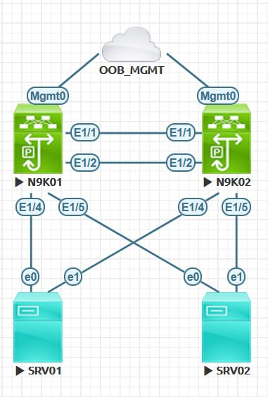
N9K01:
feature interface-vlan
feature hsrp
feature lacp
feature vpc
vlan 100,200
vpc domain 1
interface ethernet 1/1-2
switchport
  switchport mode trunk
channel-group 1 mode active
  no  shutdown
interface port-channel 1
switchport
  switchport mode trunk
  vpc peer-link
interface mgmt 0
  no shutdown
  ip address 10.1.1.1/24
vpc domain 1
  peer-keepalive destination 10.1.1.2 source 10.1.1.1 vrf management
  peer-switch
  peer-gateway
  auto-recovery
exit
interface ethernet 1/4
switchport
  no shutdown
channel-group 4 mode active
interface port-channel 4
 switchport
 no shutdown
 vpc
switchport mode access
switchport access vlan 100
interface ethernet 1/5
 switchport
 no shutdown
channel-group 5 mode active
interface port-channel 5
 switchport
 no shutdown
 vpc
switchport mode access
switchport access vlan 200
interface vlan 100
  ip address 192.168.100.252/24
  no shutdown
  hsrp 100
    preemt
  priority 200
    ip 192.168.100.254
interface vlan 200
  no shutdown
  ip address 192.168.200.252/24
  hsrp 200
    ip 192.168.200.254
N9K02:
feature interface-vlan
feature hsrp
feature lacp
feature vpc
vlan 100,200
vpc domain 1
interface ethernet 1/1-2
switchport
   switchport mode trunk
channel-group 1 mode active
  no  shutdown
interface port-channel 1
switchport
  switchport mode trunk
  vpc peer-link
interface mgmt 0
  no shutdown
  ip address 10.1.1.2/24
vpc domain 1
  peer-keepalive destination 10.1.1.1 source 10.1.1.2 vrf management
  peer-switch
  peer-gateway
  auto-recovery
exit
interface ethernet 1/4
 switchport
 no shutdown
channel-group 4 mode active
interface port-channel 4
 switchport
 no shutdown
 vpc
switchport mode access
switchport access vlan 100
interface ethernet 1/5
 switchport
 no shutdown
channel-group 5 mode active
interface port-channel 5
 switchport
 no shutdown
 vpc
switchport mode access
switchport access vlan 200
interface vlan 100
  ip address 192.168.100.253/24
  no shutdown
  hsrp 100
    ip 192.168.100.254
interface vlan 200
  no shutdown
  ip address 192.168.200.253/24
  hsrp 200
    ip 192.168.200.254
SRV01:
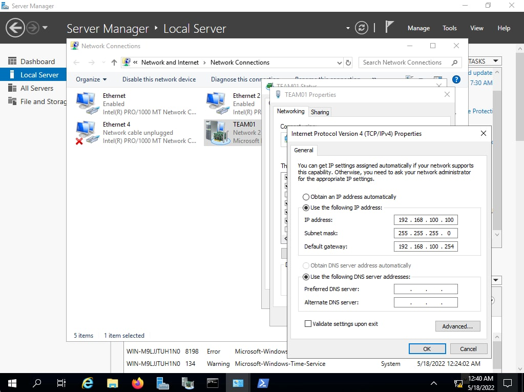
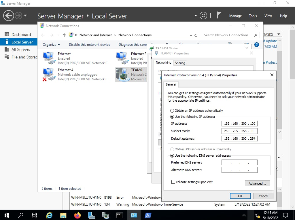
SRV02:
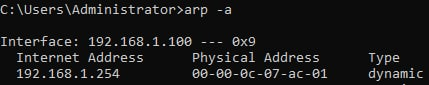
Verification on SRV01: